Voltmeter Basics
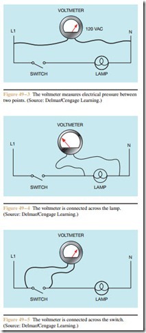
Recall that one definition of voltage is electrical pressure. The voltmeter indicates the amount of potential between two points in much the same way a pressure gauge indicates the pressure difference between two points. The circuit in Figure 49 – 3 assumes that a volt- age of 120 volts exists between L1 and N. If the leads of a voltmeter were to be connected between L1 and N, the meter would indicate 120 volts.
Now assume that the leads of the voltmeter are connected across the lamp (Figure 49 – 4).
Question 1: Assuming that the lamp filament is good, would the voltmeter indicate 0 volts, 120 volts, or some value between 0 and 120 volts?
Answer: The voltmeter would indicate 0 volts. In the circuit shown in Figure 49 – 4, the switch and lamp are connected in series. One of the basic rules for series circuits is that the voltage drop across all circuit components must equal the applied voltage. The amount of voltage drop across each component is proportional to the resistance of the components and the amount of current flow. Since the switch is open in this example, there is no current flow through the lamp filament and no voltage drop.
Question 2: If the voltmeter is connected across the switch as shown in Figure 49 – 5, would it indicate 0 volts, 120 volts, or some value between 0 and 120 volts?
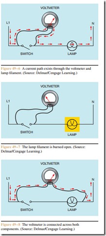
Answer: The voltmeter would indicate 120 volts. Since the switch is an open circuit, the resistance is infinite at this point, which is millions of times greater than the resistance of the lamp filament. Re- call that voltage is electrical pressure. The only current flow through this circuit is the current flow- ing through the voltmeter and the lamp filament (Figure 49 – 6).
Question 3: If the total or applied voltage in a series circuit must equal the sum of the voltage drops across each component, why is all the voltage drop across the voltmeter resistor and none across the lamp filament?
Answer: There is some voltage drop across the lamp filament because the current of the voltmeter is flowing through it. The amount of voltage drop across the filament, however, is so small as compared to the voltage drop across the voltmeter that it is generally considered to be zero. Assume the lamp filament to have a resistance of 50 ohms. Now assume that the voltmeter is a digital meter and has a resistance of 10,000,000 ohms. The total circuit resistance is 10,000,050 ohms. The total circuit current is 0.000,011,999 ampere (120/10,000,050) or about 12 microamperes. The voltage drop across the lamp filament would be approximately 0.0006 volts or 0.6 millivolts (50 OX 12 f..A).
Question 4: Now assume that the lamp filament is open or burned out. Would the voltmeter in Figure 49 – 7 indicate 0 volts, 120 volts, or some value between 0 and 120 volts?
Answer: The voltmeter would indicate 0 volts. If the lamp filament is open or burned out, a current
path for the voltmeter does not exist and the volt- meter would indicate 0 volts. In order for the volt- meter to indicate voltage, it would have to be connected across both components so that a complete circuit would exist from L1 to N (Figure 49 – 8).
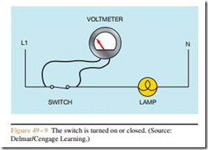
Question 5: Assume that the lamp filament is not open or burned out and that the switch has been closed or turned on. If the voltmeter is connected across the switch, would it indicate 0 volts, 120 volts or some value between 0 and 120 volts (Figure 49 – 9)?
Answer: The voltmeter would indicate 0 volts. Now that the switch is closed, the contact resistance is extremely small and the lamp filament now exhibits a much higher resistance than the switch. Practically all the voltage drop will now appear across the lamp (Figure 49 – 10).


