Measurement of DC Voltage
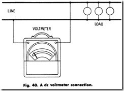
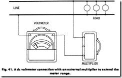
If a de voltmeter (Fig. 40) reads backward, reverse the instrument leads. Voltmeters are commonly equipped with an internal or external resistance (sometimes called a multiplier) to extend the range of the instrument. This is shown in Fig. 41.
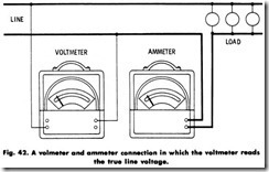
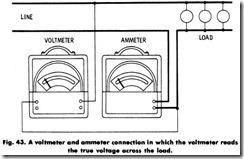
Measurement of AC Power (Voltmeter and Ammeter Method) The power in an electric circuit carrying a noninductive load may be measured by the combined use of a voltmeter and ammeter, or by means of a wattmeter. An illustration showing the connections of a voltmeter and ammeter for power measurements is shown in Figs. 42 and 43. In Fig. 42, the voltmeter measures line voltage, not load voltage. The ammeter measures load current only. In Fig. 43, the voltmeter measures load Foltage, not line voltage. The ammeter measures load current plus voltmeter current.
Measurement of AC Single-Phase Power (Wattmeter Method)
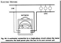
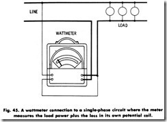
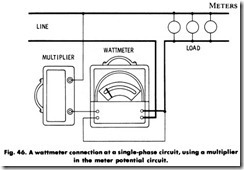
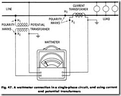
Methods of connections when power in a single-phase system is measured by a wattmeter are shown in Figs. 44 through 49. In Fig. 44 the instrument is measuring load power plus the loss in its own current-coil circuit. If the instrument reads backwards, reverse the current leads.
Special precautions should be taken not to overload wattmeters. Potential transformers are usually employed on circuits above 300 volts. On circuits of 750 volts and above, both potential and current trans formers are generally used. Always ground the secondary of both transformers.
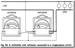
Figs. 48 and 49 illustrate the connections when it is desired to measure the voltage and power consumption of the load simultaneously. In Fig. 48, the wattmeter measures load power plus losses in the voltmeter and wattmeter potential circuits. In Fig. 49, the wattmeter measures load power plus losses in its own current-coil circuit.
Power Factor Measurement (Indirect Method)
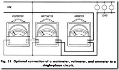
The power factor of a single-phase load may be determined by dividing the wattmeter reading by the product of the voltmeter and ammeter readings. When the instruments are connected as shown in Fig. 50, the wattmeter measures load power plus losses in the ammeter and wattmeter current-coil circuits. In Fig. 51, the wattmeter measures the sum of the power losses of the load, the potential circuit of the wattmeter, and the voltmeter.
Power-Factor Measurement (Direct Method)
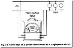
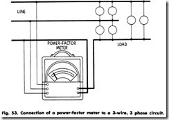
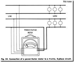
A more convenient method for direct reading of the power factor in single and polyphase circuits by means of power-factor meters con nected as shown in Figs. 52, 53, and 54. These connections, when made as shown, are correct at all power factors. Polyphase power-factor meters are intended for use in balanced circuits only. Single-phase power-factor meters should be used only at the calibrated frequency.
Polyphase Power Measurement
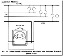
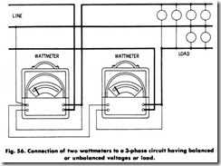
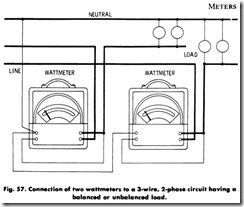
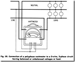
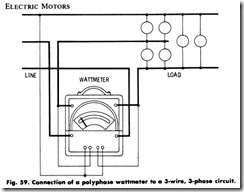
Illustrations showing connections for power measurement in poly phase systems are shown in Figs. 55 through 59. In Fig. 55 the power of the system is three times the indication on the wattmeter. The meter indicates its own potential losses plus the power in one phase of the load. In Fig. 56, the two wattmeters will not indicate alike except at unity power factor. Above 50% power factor, the three-phase power is the sum of the two readings. Below 50% power factor, it is necessary to reverse the reading of one wattmeter (by reversing its current leads) and then take the difference between the readings of the two instruments.
METER MAINTENANCE
Electric meters will give good service if accorded the care which mechanisms of their delicacy deserve. If mistreated, they may fail to function properly and considerable loss in both time and money may result. It is therefore of the greatest importance that thoughtful attention be given to their care and use.
Selection
Best results in the use of instruments depend on the proper original selection. The accuracy desired and the cost are the two important factors in selection. Instruments should be chosen to give the required accuracy at the lowest cost.
The following guide for proper instrument selection is recommended:
1. What accuracy is desired?
2. Should it be ac or dc?
3. Should it be portable or for switchboard mounting?
4. Should it be indicating or recording?
5. What is the desired rating? The range should be such that the normal readings are above one-third scale.
6. If a switchboard instrument is desired, should it be of the surface mounting or semiflush mounting type?
7. Can a standard instrument listed in the manufacturer’s catalog be utilized in order to obtain the lowest cost and the best delivery?
8. What effect will the instrument have on the circuit in which it is to be used? For example, some applications require a voltmeter with high resistance for minimum current drain. Or, an ammeter may have to have a low volt-ampere rating if it is to be used with a through-type current transformer.
9. Conditions under which the instrument is to be used are impor tant. Indoor or outdoor humidity or other corrosive atmosphere may require special instruments.
Instrument Use
When any questions arise as to the use of a specific instrument, it is recommended that the information be obtained from the manufacturer.
The following pointers should be observed before placing any in strument in service:
1. The manufacturer’s instruction book accompanying the instru ment should be read carefully.
2. . The instrument should be handled carefully to avoid any vibration or shocks which may injure the bearings in the meter movement.
3. Estimate the value of the current, voltage, etc., to be measured from the nameplate of the apparatus on which the measurement is to be made.
4. If an instrument has more than one tap or range, make connection to the highest range first to avoid damage to the instrument.
5. Instruments should always be read when in their normal operating
position; that is, portables should be in a level, horizontal posi tion; switchboard types in a vertical position.
The following pointers should be observed before placing any port able instrument in service:
1 . Metal benches should be avoided, as the instrument indication may be affected by the proximity of the metal.
2 . Proper-sized leads should be used. Terminals should be clean to avoid high contact resistances, particularly in the case of meters used with shunts. Lead wires should extend away from the observer to avoid accidentally pulling the instrument off the table.
3 . Whenever a shunt is used with a meter to read current, always check to make sure the leads with which the instrument was calibrated are being used.
4 . If external-resistance multipliers are used, check both the serial number of the instrument and that of the multiplier to make sure of the correct combination.
5 . The instrument zero setting should be checked. If the pointer is slightly off zero, reset to zero by adjusting the external-zero shifter. Never try to compensate for a bent pointer by moving the zero shifter.
6 . The instrument should not be used in strong fields such as near cables or bus bars. Presence of a magnetic field which is affecting the reading of an instrument can be detected by turning the instrument (clockwise or counterclockwise) 90° at a time, and taking a reading in each position. If a difference is noted in the readings, some stray field is present.
7 . Unshielded instruments should not be placed closely together, as the reading of one instrument may be affected by the magnetic field of the other.
8 . When an ammeter or shunt is to be connected into a circuit, always connect it into the grounded side, if possible.
9 . When a voltmeter is to be connected to a circuit, always connect the leads to the instrument first. This avoids loose leads which may be hot. Be sure that voltmeter leads are properly insulated for the voltage to be checked.
10 . Instruments, shunts, and leads should always be arranged in such a way that there is no danger of knocking them off the table or tripping over the lead. If any high voltages are to be measured, the arrangement should be such that no one might accidentally touch the high-voltage equipment.
11 . Whenever an instrument is to be connected to a current-trans former secondary, always short-circuit the secondary terminals before the primary is connected in the circuit to avoid dangerously high voltages. The current-transformer secondary must be grounded.
12 . When a potential transformer is to be used, always make sure that the instrument is connected to the secondary, or low-voltage, side. The potential-transformer secondary circuit must be grounded.
The following pointers apply to switchboard instruments:
1. Switchboard instruments should be mounted on panels in accord ance with the manufacturer’s instructions.
2. Never mount a switchboard instrument on a panel until all other work on the panel is completed, as any pounding or vibration may affect the instrument.
3. The general precautions given earlier for portable instruments also apply to switchboard instruments.
Instrument Precautions
The following pointers should be observed in the use of any electric instrument:
1. Always try to have the instrument reading between 1/2 and 3/4 full scale. Never read below 1/3 full scale if it can be avoided.
2 . Never touch bare terminals or binding posts while an instrument is energized.
3 . The instrument reading should be made from directly above the scale to avoid errors.
4 . If a split-core current transformer is used with an ammeter, always make sure that the transformer-core joint is free from dirt, which may introduce a considerable error in the reading.
5 . To avoid errors, instruments should never be used in extreme temperatures. Special temperature-compensated instruments are used for these conditions.
6 . Special instruments should be used to measure motor-starting currents or welding currents.
7 . Clean the glass of an instrument by using a damp cloth. A dry cloth may induce a static charge on the glass and affect the instrument reading. If the instrument glass does become charged, the charge can be dispelled by breathing on the glass.
8 . Never slam the cover of an instrument. Be sure the nuts of the binding post are tight, even when the instrument is not in use.
9 . If an instrument is overloaded or dropped, or if for any reason the accuracy is doubted, the instrument should be checked against
another instrument at several different readings before it is used again.
10 . Tapping an instrument with the fingers will remove any slight stickiness. If the pointer movement is erratic, and if tapping causes appreciable movement of the pointer, the instrument bearings may require attention and should be examined by a competent instrument-repair laboratory.
11 . Instrument accuracy is always expressed in terms of the percent
age of error at the full-scale point, so maximum accuracy is obtainable by keeping the reading as high on the scale as possible. This calls for the selection of a properly rated instrument. The accuracy of the readings is determined as follows: Assume that there are 100 scale divisions and that the accuracy is 1% of full scale. A scale reading of 100 means that the quantity measured contains 100 units plus or minus 1 scale division; that is, the correct value lies between 99 and 101 units. However, while a scale reading of 20 (1/5 of full scale) also has a margin of error of plus or minus 1 division, the error there is 5 times as great, or plus or minus 5%.
12 . Wattmeters should be so connected into a circuit that the current coil and the potential coil are at the same potential. (The potential terminal, which is connected in the same side of the line as the
current coil, is usually identified by a zero or +marking.) This is particularly important where multipliers are to be used, as it is possible to obtain a potential difference between the current and potential coils high enough to cause a breakdown.
13 . Instruments with single ratings are preferable because if, by accident, the single-rated instrument becomes defective, the use of only one instrument is lost, whereas if one tap of a multirated instrument burns out, the entire instrument has to be repaired.
14 . Where rectifier instruments are used in ac circuits to measure acvalues, the shape of the waveform should be known, as rectifier instruments are normally calibrated for sine waves only.
Instrument Calibration
How often an instrument should be calibrated depends entirely on its use and accuracy desired. If calibration standards and equipment are not available, instruments of nearly the same rating can be checked against each other. If wide discrepancies are noted, the instrument which reads incorrectly should be checked by a competent laboratory technician or returned to the manufacturer for correction.
If the meter or instrument requires a new bearing or jewel, it is advisable to replace the pivot as well, as the old one may have become damaged, especially if the meter has been operating with a damaged jewel. When inserting a new jewel, or when replacing a jewel after having removed the moving element, see that the top bearing clamping screw is loosened so that this bearing is free to move, thereby prevent ing the possibility of a damaged jewel or shaft. See that the top bearing is properly set and clamped after inserting and adjusting the lower bearing.
To replace the pivot, remove the jewel screw from the meter and insert the pivot wrench in place. Clamp the pivot in the end of the wrench and unscrew. Replace the pivot with a new one and screw it into the shaft. Apply a drop of fine watch oil to the jewel and insert the new jewel screw. Whenever the registering element of a meter is oiled, it should be wiped carefully to remove any excess oil. Only the best quality of watch or instrument oil must be used for this purpose.
SUMMARY
Meters are often a part of the control equipment for electric motors and generators. They are also used extensively in the maintenance and repair of all types of electrical equipment . For this reason, persons using meters should be thoroughly familiar with their construction, capabili ties, limitations, and use.
The most common meters used in conjunction with motors and generators are ammeters, voltmeters, and wattmeters. These may be direct-current or alternating-current instruments. In addition, they may operate on a permanent-magnet, moving coil, a dynamometer, a mag netic- vane, or an induction principle.
Ammeters should never be connected across a voltage source, but always in series with the device of which the current is to be measured. Placing an ammeter across a voltage source will result in permanent damage to the instrument. The range of ammeters can be extended by means of shunts.
Voltmeters should always be connected across (in parallel with) the part of the circuit in which it is desired to determine the voltage.
Do not place the voltmeter in series with the device as an inaccurate reading, if any, will result. The range of voltmeters can be extended by the use of multipliers.
Clamp ammeters are often used where absolute current values are unnecessary. This type of instrument is useful because it measures the approximate amount of current flowing in a conductor without the necessity of disconnecting the wire and inserting the meter.
All meters are relatively delicate instruments and should be used and handled with great care. Rough handling or improper use may result in permanent damage or inaccurate readings. An inaccurate reading is worse than no reading as it may lead to the wrong conclusions.
The proper use of a meter requires the user to be thoroughly familiar with the instrument as well as the electrical circuits and equipment on which it is used. The instruction book supplied by the manufacturer should be followed explicitly to prevent error, damage, and loss of time.
REVIEW QUESTIONS
1. How should an ammeter be connected to measure current?
2. What is the correct method of connecting a voltmeter?
3. How can the range of an ammeter be extended?
4. How does a dynamometer-type meter read true or effective values?
5. How can a permanent-magnet, moving coil meter be modified to allow readings to be taken on ac circuits?
