Test Procedure Example 1
The type of problem determines the procedure to be employed when troubleshooting a circuit. For example, assume that an overload relay has tripped several times. The first step is to determine what conditions could cause this problem. If the overload relay is a thermal type, a source of heat is the likely cause of the problem. Make mental notes of what could cause the overload re- lay to become overheated:
1. Excessive motor current.
2. High ambient temperature.
3. Loose connections.
4. Incorrect wire size.
If the motor has been operating without a problem for some period of time, incorrect wire size can probably be eliminated. If it is a new installation, that would be a factor to consider.
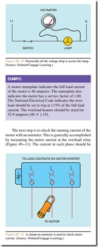
Since overload relays are intended to disconnect the motor from the power line in the event that the current draw becomes excessive, the motor should be checked for excessive current. The first step is to determine the normal full load current from the nameplate on the motor. The next step is to determine the percentage of full load current setting for the overload relay.
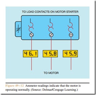
measured. If the motor is operating properly, the readings may not be exactly the same, but they should be close to the full load current value if the motor is operating under load, and relatively close to each other. In the example shown in Figure 49 – 12, phase 1 has a cur- rent flow of 46.1 amperes, phase 2 has a current flow of 45.8 amperes, and phase 3 has a current flow of 45.9 amperes. These values indicate that the motor is operating normally. Since the ammeter indicates that the motor is operating normally, other sources of heat should be considered. After turning off the power, check all connections to ensure that they are tight. Loose connections can generate a large amount of heat, and loose connections close to the overload relay can cause the re- lay to trip.
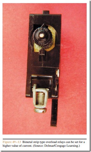
Another consideration should be ambient temperature. If the overload relay is located in an area of high temperature, the excess heat could cause the overload relay to trip prematurely. If this is the case, bimetal strip type overload relays (Figure 49 – 13) can often be adjusted for a higher setting to offset the problem of ambient temperature. If the overload relay is the sol- der melting type, it will be necessary to change the heater size to offset the problem, or to install some type of cooling device such as a small fan. If a source of heat cannot be identified as the problem, the overload relay probably has a mechanical defect and should be replaced.
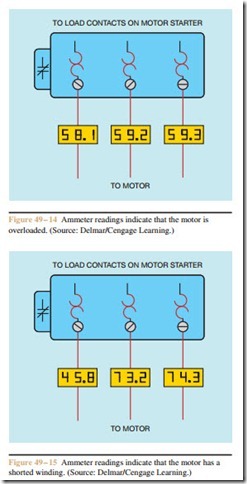
Now assume that the ammeter indicates excessively high current reading on all three phases. In the Figure 49 – 13 Bimetal strip type overload relays can be set for a higher value of current. (Source: Delmar/Cengage Learning.)
example shown in Figure 49 – 14, phase 1 has a current flow of 58.1 amperes, phase 2 has a current flow of 59.2 amperes, and phase 3 has a current flow of 59.3 amperes. Recall that the full load nameplate current for this motor is 46 amperes. These values indicate that the motor is overloaded. The motor and load should be checked for some type of mechanical problem such as a bad bearing or possibly a brake that has become engaged.
Now assume that the ammeter indicates one phase with normal current and two phases that have excessively high current. In the example shown in Figure 49 – 15, phase 1 has a current flow of 45.8 amperes, phase 2 has a current flow of 73.2 amperes, and phase 3 has a current flow of 74.3 amperes. Two phases with excessively high current indicate that the motor
probably has a shorted winding. If two phases have a normal amount of current and one phase is excessively high, it is a good indication that one of the phases has become grounded to the case of the motor.


