Distributed systems
Parallel and serial communications
Cabling is one of the most costly parts of any control scheme. There is the cost of the cable itself, the support structure and cable tray, plus the labour costs of pulling cable, ferruling and terminating the ends. If, in the course of commissioning, it is discovered that some extra signals are needed and there are insufficient spare cores, another expensive cable will have to be pulled, with all the attendant costs and time delay.
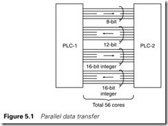
Figure 5.1 shows two PLC systems that need to exchange data. As shown there are eight signals one way, 12 signals the other at 110 V AC, and two 16-bit numbers at 24 V DC. Along with supplies, neutrals and DC returns this represents 56 cores needing, probably, one 27 core and one 37 core steel wire armoured cable, 3 off 110-V 8-bit digital output cards, 3 off 110-V 8-bit digital input cards, 2 off 24-V digital output cards and 2 off 24-V digital input cards. All the cards require labour to terminate them inside the cubicles at each end. All told, it is not a cheap exercise.
Examples similar to Figure 5.1 are common. At my plant there are arc furnaces (each controlled by PLCs) whose fume extraction is handled by baghouses (each controlled by a separate PLC). The two PLCs for each furnace need to exchange information so the fume extraction can set its fan speeds, suction level, etc. to the furnace performances, and to ensure that each furnace is interlocked with the baghouse operation.
In Chapter 1 we described how remote I/O can be used to reduce cabling costs. In this chapter we will see how similar ideas can be developed to provide communication between PLCs, computers and intelligent instruments.
Figure 5.1 is a form of parallel transmission; all the data to be sent are passed simultaneously. This method is widely used (at lower voltages) to connect computers to printers and for bus-based computer instru- mentation schemes such as the IEEE-488 bus described in Chapter 7.
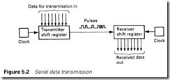
In Figure 5.2 a single data line (plus a return) connects the transmitter and the receiver, and the data are transmitted as a serial string of bits. Since computers, peripherals, PLCs, etc. all work internally in parallel for speed, parallel to serial conversion is required at the transmitter and serial to parallel conversion at the receiver. The simplest way of achieving this is to use shift registers as shown in Figure 5.2, into which data can be loaded in parallel and shifted out one bit at a time. Specialist integrated circuits called UARTs (universal asynchronous receivers–transmitters) are used to provide this conversion and the control functions. Not surprisingly, this is known as serial transmission.
The advantages of serial transmission arise from cost and flexibility. All that needs to be installed for bidirectional communication is a small, cheap, usually four-core (two pair) screened cable, although the signal
levels are small and there is usually a cost penalty in that trunking or conduit needs to be used for protection.
Once installed, a serial communication system is not really constrained in the amount of data that can be passed (although there will be a time penalty for large amounts of data). Additional data items can be added with no installation costs.
The disadvantages are speed, noise immunity, safety and program comprehensibility. Serial communication is obviously slower than parallel transmission (by a factor equal to the number of parallel lines). This is generally not a problem; on a dedicated PLC communication system a response time of 0.5 s is easily achievable (and remote I/O systems normally achieve around 30 ms). Response times can be longer on com- mercial systems such as Ethernet, but these are generally not interfacing directly with human beings or a plant in time-critical applications.
The voltages in serial transmission are low, usually of the order of 10 V, and hence prone to noise. Care needs to be taken in the installation (conduit or trunking, separation and screening are advisable) and pro- prietary systems include methods for error detection and repetition of faulty messages.
Despite these error-detecting correction schemes, a serial communi- cation system should never be considered totally secure, and must not be used for purely safety functions such as emergency stops. These must always be hardwired. We will return to safety considerations in Chapter 8.
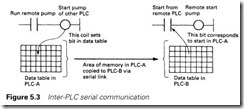
Finally we have program comprehensibility. The idea of serial com- munications can be difficult to comprehend in the middle of a fault at 3.00 a.m. Essentially, what we are achieving is to link two areas of memory in separate PLCs as shown in Figure 5.3. This added complexity can bring great confusion if it is not supported by good plant documen- tation.
Serial standards
Introduction
For a serial communication system to work, there needs to be a consistency between the transmitter and the receiver. There must be definition of:
1 Signal voltage levels.
2 The transmission code (what the bit patterns mean and how the message is built up).
3 Transmission rates (the speed at which the bit pattern is sent).
4 Synchronization. In Figure 5.2 we showed clocks at both ends of the link. If these have a small difference in frequency (as they inevitably will) the receiver will get out of alignment with the transmitter. Some method must be provided to give synchronization between transmitter and receiver.
5 Protocols. Apart from the data, there will need to be some method for the transmitter and receiver to interchange control signals such as ‘I am unable to receive a message at present’.
6 Error-checking methods and recovery procedures (‘that last message didn’t make sense, please send it again’).
Getting equipment from different manufacturers to work together over a serial link can sometimes be very difficult. The problems usually arise out of differences in one (or more) of the above points.
Synchronization
The theoretically simplest way to achieve synchronization is to have a common clock for both the transmitter and the receiver, as the two can never, in theory, get out of alignment. This is known as synchronous transmission.
Most systems, however, are asynchronous, and use separate clocks, as in Figure 5.4. The messages are broken down into characters
(typically 5–8 bits in length) and the two clocks are synchronized at the start of each character.
The idle state of the line is a ‘1’ signal (called a ‘mark’ in telecommu- nications). The character starts with a ‘0’ signal (called a space) followed by the data bits, usually with least significant bit first. An error-correcting bit (called the parity bit) is sometimes added after the data bits. This is discussed in Section 5.2.7. Finally, the signal returns to the idle mark state for a time before the next character can be sent. This is known as the stop bit and can be 1, 1.5 or 2 bits in width, depending on the system. The next character can follow a random time after the stop bit. The transmitter and receiver clocks are synchronized at the start bit, and only have to stay aligned for the 10 or so bits needed to send a character. It may be thought that, with noise, mark to space transitions in the data could be mistaken for start bits. In practice, the link will pull itself back into synchronization in a few characters as shown in Figure 5.5.
A framing error is signalled by the UART when it receives a zero where it would expect a stop bit.
Character codes
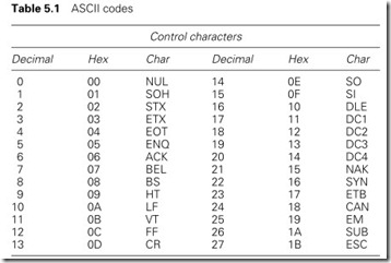
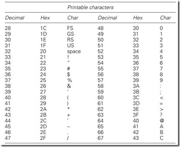
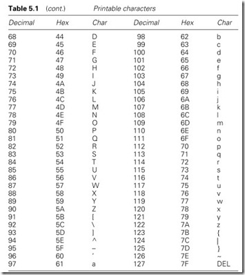
Many types of character code have evolved over the years, but now the almost universal standard is the ASCII code (American Standard Code for Information Interchange, also known as ISO 646) shown in Table 5.1. Variations on this are the CCITT alphabet No. 5, and national options such as the £ symbol in the UK.
ASCII is a 7-bit code giving 128 different combinations covering full upper/lower case alphanumeric characters along with punctuation and 32 control characters that we will return to in Section 5.2.6.
Transmission rates
The transmission signalling rate is expressed in baud, which is the number of signal transitions per second. For the majority of serial links that we shall consider, with two signalling states (0 and 1), the baud rate and the bits/s are identical. For linking a PLC with an instrument, a rate of 1200 baud might be typical. For proprietary PLC to PLC or remote I/O links, with high-quality communication cable, rates as high as 115 kilobaud will be used.
This should not be interpreted as an ability to send 115 000 bits of data down the cable in 1 s. We have already seen in Figure 5.4 that splitting the data into characters with start/stop bits involves some overheads, which increase with the error checking when full messages are sent.
Control characters can be obtained via the use of the CONTROL key and the character in the right-hand column. Backspace (BS) for example is ctrl-H.
Modulation of digital signals
So far we have considered a serial link transmitting digital data in its ‘raw’ form, i.e. as a series of voltage levels directly representing the bit pattern we wish to send. This is known as the baseband transmission.
A digital signal has a bandwidth from 0 Hz (DC corresponding to a string of continuous zeros or ones) to at least half the bit rate. Many transmission media, such as radio telemetry and the telephone network, have inherent low-frequency limitations and cannot handle baseband signals.
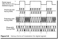
The data are therefore modulated onto a carrier wave. There are three different ways of achieving this: amplitude shift keying (ASK),
frequency shift keying (FSK) and phase shift keying (PSK). All are summarized in Figure 5.6. One advantage of modulation is that it allows several independent signals, modulated onto different carrier frequencies, to be carried on the same cable. A modulated digital signal is said to be using broad band or carrier band transmission. Often the term ‘carrier band’ is used to imply FSK with one signal on the cable, and ‘broad band’ is used where several signals share the cable.
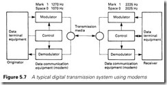
Broad band and carrier band both require devices to interface the digital signals at the receiver and transmitter to the transmission media. These modulate the signal at the transmitter, and demodulate it again at the receiver. Such devices are known as modulators/demodulators or modems.
Figure 5.7 shows a typical two-way arrangement using the public telephone network and FSK. ‘Originator’ refers to the station which originally established the link; subsequent communications are bidirec- tional.
In Figure 5.7 there are two types of equipment whose names, and more commonly abbreviations, appear widely in data transmission and are the source of much confusion. The equipment at the transmitting and receiving ends is known as data terminal equipment (DTE). This covers computers, PLCs, printers, terminals, VDUs, graphics displays, etc. The communication equipment (i.e. the modems) is known as data communication equipment (DCE).
The confusion arises because communication standards and protocols are concerned with connecting a DTE and a DCE. When we link a PLC
and a printer we are linking two DTEs, and will probably have difficulties. We will return to this problem in the following section.
Standards and protocols
RS232E
For successful communications to take place, a set of rules must exist to govern the transmission of data. These rules can be split into standards, which govern voltage levels, the connection and control of DTE–DCE interface, and protocols, which determine the content and control of the message itself.
Much of the early work on data transmission was done by the Bell Telephone company in the USA, and the result of their work was formalized by the Electrical Industries Association (EIA) into ‘A stand- ard for the interface between DTEs and DCEs employing serial binary interchange’. This standard is known as RS232 and is currently at revision E.
Worldwide standards are set by the Comite Consultatif International Telephonique et Telegraphique (CCITT), which is a part of the United Nations International Telegraph Union. The CCITT publishes standards and recommendations, those for data transmission being prefixed by letters V or X. Standard V24 is, for all practical purposes, identical to RS232.
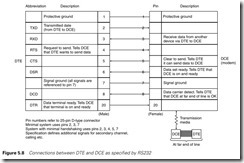
Signal levels defined for RS232 and V24 are +6V to +12 V at the source for a space (zero) and -6V to -12 V for a mark (one). These are allowed to degenerate to +3V and -3 V at the receiver. Other character- istics such as line capacitance and edge speeds are also defined. The connections are made with a 25-pin D-type connector. Figure 5.8 summarizes the main connections between a DTE and a DCE and the
meanings attached to each. These are only a subset of the full specification (which is a rather lengthy document and very heavy going).
There are many common sources of trouble with ‘standard RS232’. The standard covers the connection of a DTE and a DCE. Connecting a PLC to a printer is linking two DTEs. Theoretically, a ‘null modem cable’ which crosses signals such as pins 2 and 3 (data transmit and receive) should work, but usually does not. Manufacturers usually assign their own, often peculiar, ideas to the pin allocation. Many printer manu- facturers, for example, use pin 2 to receive data and make the printer a DCE. Even IBM use a 9-pin D-type connector (rather than the stand- ard 25 pin) for RS232 connections on their AT range of computers. Acorn (for reasons known only to themselves) used a 4-pin DIN plug on their BBC computer, and this has proliferated into other equipment. Allied with this is an almost random interpretation of the use of the control signals. It is not unknown for an ‘RS232-compatible instrument’ to have just two connections (corresponding to pins 2 and 7 on the DTE
in Figure 5.8). Such a device can have no data flow control at all. ‘RS232 compatible’ thus nearly always means an extended period
with a breakout box or line analyser (both essential equipment for use with serial links) and a collection of crimp plugs/sockets and D-type shells. We will return to this problem in Section 5.2.8.
RS422 and RS423
RS232 was designed for a short-haul link between a DTE and a DCE, usually within the same room. If RS232 is used at high speeds over long distances (greater than a few metres), problems will occur.
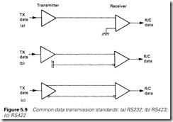
The EIA have acknowledged the limitations of RS232 for DTE/DTE communications, and have issued two other standards, illustrated in Figure 5.9. One major problem with RS232 is the referencing of signals to a common ground (pin 7 in Figure 5.8) as in Figure 5.9(a). RS423 and RS422 (Figure 5.9(b) and (c)) use differential receivers to dispense with the ground connection and overcome common mode noise.
Nominal transmitter voltages are ±6 V with the signal sense being determined by the relative polarity. Connection A is negative with respect to B for a mark (one) and vice versa for a space.
RS423 uses a single-ended transmitter and a differential receiver, allow- ing a standard RS232 transmitter to be used provided the difference in ground potentials does not exceed 4 V. RS422 uses both a differential transmitter and receiver. The mechanical (37-pin connector) details are defined in RS449.
The 20 mA loop
An unofficial early ‘standard’ is the 20-mA loop. This originated with the early electromechanical teleprinters, but is still found in many
applications. It consists of a switch driven by data at the transmitter, a current source, and a current sensor at the receiver. Presence of current is a mark (one) and absence a space (zero).
The current loop, isolated from earth, gives good common mode noise immunity, and overcomes differences between ground potentials at either end of the loop. This is the main reason for its continued use.
Unfortunately there are no common standards for control, or even which end of the loop provides the current source. Figure 5.10(a) is known as active transmit, passive receive, and Figure 5.10(b) is passive transmit, active receive. Little communication can take place between a passive transmitter and a passive receiver.
Message protocols
The standards described above cover the ‘mechanics’ of data transmission. The message content is defined by the protocol used. In addition to defining the form of a message (i.e. what group of bits form characters, and what groups of characters form a message), the protocol must define how communication is initiated and terminated, and what actions must be taken if the link is broken during a message. The protocol must also cover how errors are detected, and what action is then to be taken.
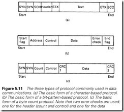
There are essentially three types of protocol in use, as shown in Figure 5.11. Character-based protocols (Figure 5.11(a)) use control characters from the ASCII set of Table 5.1 to format the message. Most character-based protocols are based, to some extent, on IBM’s BISYNC standard.
Bit pattern protocols, such as IBM’s SDLC and ISO’s HDLC and CCITT X 25, are based on Figure 5.11(b). Flag characters define the start and end of the message, with the end flag being preceded by some form of error control.
The final type of protocol uses a byte count. The start of the message is signalled by a start flag character followed by a count showing the total number of characters in the message. The receiver counts in the
message characters and then validates the message with the error- checking data. A common example of this type of protocol is DEC’s DDCMP.
Of these, character-based protocols which are variations on BISYNC are probably most commonly used (sometimes called BSC for binary synchronous protocols). They are easy to implement and have the advantage that they can be monitored with a simple terminal across the signal lines.
The control characters from the ASCII set commonly used are:
· Hex 04 EOT End of transmission (often used as a reset to clear the line).
· Hex 16 SYN Synchronizing character, establishes synchronization
(i.e. start) and sometimes used as a fill character.
· Hex 05 ENQ Enquiry, used to bid for the line in a multidrop system
(see Section 5.3.4).
· Hex 02 STX Start of Text. What follows is the message.
· Hex 01 SOH Start of header. What follows is header information, e.g. message type.
· Hex 17 ETB End of transmission block. Data commenced with STX or SOH is complete.
· Hex 03 ETX End of text. Data commenced with STX or SOH is
complete and the end of a sequence block. ETX is normally followed by some form of error-checking information, which is validated by the receiver which replies with either:
· Hex 06 ACK Acknowledgement. Message received error free and I am ready for more data. Also used to acknowledge selection on a multidrop system (see later), or:
· Hex 15 NAK Negative acknowledgement. Message received with errors, please retransmit. Also used to say ‘not available’ when selected on a multidrop system.
Error control
The addition of noise to a digital signal does not necessarily result in corruption. The original signal can be regenerated at the receiving end providing the noise has not been sufficiently severe to turn a ‘1’ into a ‘0’ or vice versa.
Noise generally has a power density distribution similar to that of Figure 5.12, with zero mean and tails going off to infinity. If the digital signal has voltage levels +V and 0 V, noise in region A will corrupt a ‘0’ to a ‘1’, and noise in region B will corrupt a ‘1’ to a ‘0’. The probability of error is thus the sum of areas A and B divided by the total area under the curve.
This probability depends on the ratio between the magnitude of the signal and the noise. The signal to noise ratio, SNR, is defined as:
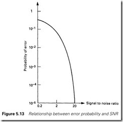
An SNR of 20 is normally achievable. There is, however, no ‘cut-off’ value for noise, and there is a possibility of error whatever the value of SNR. This probability can be calculated (using statistical mathematics) and has the form of Figure 5.13. From this graph, a link with an SNR of 20 will have an error rate of 10-5. This sounds good, but it represents some 30 corrupt bits in the transmission of a 360 kbyte floppy disk (which contains 2.88 Mbits).
Rather interestingly, as the signal gets swamped by noise (SNR < 1) the error rate does not tend to 1 (as might be first thought) but 0.5. What will be received will be a random stream of ‘1’s and ‘0’s, half of which will, on average, be correct by chance.
With even higher SNRs, 100% reception cannot be guaranteed. A single bit in error can have severe results, changing the sign of a number, or turning an ‘open’ command to a ‘close’ command, so some form of error control is generally needed.
An error rate of 1 in 105 implies a single error bit followed by 99 999
correct bits. This is not a true picture. Anyone who has used a phone will be aware that interference normally has the form of ‘clicks’ or ‘pops’ introduced by the switching of inductive loads local to the line. This is similar to the noise found on data transmission lines. A click of 0.05 s is ignored in speech, but represents the demise of 60 bits of data at 1200 baud. Noise, therefore, tends to introduce short error bursts separated by periods of error-free transmission, and the error rate represents the average over an extended period of time.
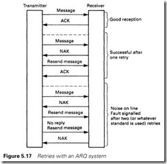
There are generally two ways of handling error control. The simplest, used in almost all industrial systems, detects that an error has occurred, and the receiving station asks for a retransmission. This is known as automatic transmission on request, or ARQ. The ASCII characters ACK (received OK) and NAK (received with errors, please send again) are used for handshaking and control.
The second method attempts to detect and correct any errors by adding redundant characters into the message. This is known as forward error control (FEC). The English language contains a lot of redundancy (allowing communication by speech in difficult circumstances). Given the sentence:
Tod?? t?e w?a??er ?s su??y
which has an error rate of 40%, and the fact that it is a statement about the weather, it is quite straightforward to fill in the missing characters to give ‘Today the weather is sunny’.
FEC is needed for radio links to and from satellites and is also used for the page addressing on Teletext (which uses a technique called the
Hamming code). It adds significantly to the message length, and is con- sequently not widely used in industrial networks.
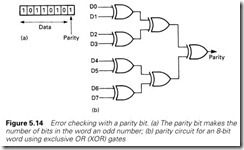
The simplest form of error detection is the parity bit. This is an extra bit added to ensure that the number of bits in a single character or byte is always odd, as shown in Figure 5.14(a). This is known as odd parity; even parity (parity bit added to make number of bits in each character even) is equally feasible, but odd parity is more commonly used. An ASCII character has 7 bits, so the addition of a parity bit increases the length to 8 bits.
Parity is easily calculated with exclusive OR gates as shown for an 8-bit character in Figure 5.14(b). Parity-calculating ICs are readily avail- able, such as the TTL 74180 and the CMOS 4531.
Parity (or, to give it its full title, vertical parity check) can detect single (or 3, 5, 7) error bits, but will be defeated by an even number (2, 4, 6) of error bits.
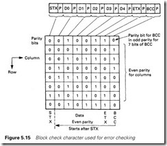
Additional protection can be provided by breaking the message down into blocks, each character of which is protected by a parity bit, and following the block with a block check character (BCC) which contains a single parity bit for each column position as shown in Figure 5.15. Normally, even parity is used for the column parity bits. This is known as longitudinal parity checking. The BCC character has its own odd parity bit which is calculated from the BCC character, not the parity bits in the message. The initial STX or SOH are excluded from the BCC calculations, but the terminating ETB or ETX are included.
BCC can detect all odd numbers of errors, and many multiple-bit combinations. It is defeated by an even number of errors spaced sym- metrically around the block.
The most powerful error detection method is known as the cyclic redundancy code (or CRC). Like the BCC method, this splits the message into blocks. Each block is then treated like a (large) binary number which is divided by a predetermined number. The remainder from this division, called the CRC, is sent as a 16-bit number (two char- acters of 8 bits) after the message. The same calculation is performed at the receiver, errors being detected by differences in the CRC.
The calculation of the CRC is performed with a shift register and exclusive OR gates, a typical example being the CRC-CCITT circuit of Figure 5.16.
A similar scheme, used on GEM-80 links, detects:
· all single-bit errors
· any odd number of errors
· all single and double errors in the GEM message format
· any two burst errors of two bits in the GEM message format
· any single burst of 16 bits or less
· all but 1 in 32 768 bursts of exactly 17 bits
· all but 1 in 65 536 bursts of greater than 17 bits
The use of CRC-checked blocks greatly improves the error rate. Typical improvements of the order of 105 are achieved, giving an undetected error rate of 1 in 1010 for a circuit with a basic error rate of 1 in 105.
Normally, ARQ systems provide an acknowledgement or an error signal to the initiating device or procedure at the transmitting end, good reception being determined by the reception of the ACK from the receiver. On receipt of a NAK (or no reception of ACK or NAK within a predetermined time) the transmitter will resend the message. To stop a line being clogged with retries, it is usual to set a limit on the number of retries (often three or five) before an error is declared. This procedure is summarized in Figure 5.17.
Point to point communication
A PLC is often required to establish a simple serial link with a device. Typical applications are reading data from an instrument or a bar code
reader, or sending data as a setpoint to an instrument or producing a report on a printer. In this section we will look at how this can be achieved with a typical device, an Allen Bradley 1771-DA ASCII module which communicates with the PLC-5 via the BTW and BTR instructions discussed in Section 4.4.5. Other manufacturers’ PLCs operate in similar (but of course not identical) manner. It should be appreciated that the description below is a vast simplification of the actual operation, and serves only to outline the principles (the manual is 150 pages long).
Point to point links are usually simple, employing, at most, parity checks for error control. Where data are being read from an instrument, the port on the instrument was probably designed to be connected to a printer, and few, if any, of the control signals on Figure 5.8 will be used. The first step for reading or writing data is therefore to determine:
(a) the connections on the instrument/device
(b) the baud rate
(c) the data format (ASCII, number of bits, parity used, number of stop bits)
(d) the way the control signals are used
(e) how message transfer is initiated (when reading data) (f) the form of the message
Fortunately (and rarely!) the ASCII module is pinned, and can behave as a pure DTE. Its operating parameters (baud rate, etc.) are set up with data sent from the PLC via a BTW instruction.
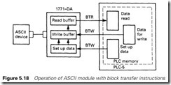
The module operation is summarized in Figure 5.18. Data to/from the outside world are buffered. The total size of these buffers is 2K bytes, the split between input and output sizes being set as part of the BTW configuration.
Data from the outside world come into the input buffer, and are passed to a block of store in the PLC-5 with a BTR instruction. Data to the outside world are written to the output buffer with a BTW instruction. A typical input message could come from a temperature transducer with the form of Figure 5.19. We need to know when a message has been received. The message will be read into the input buffer from the instrument, and the PLC allowed to perform a BTR in two circumstances:
1 When the buffer is full (i.e. the buffer has been sized exactly to the size of the data message), or
2 A character predefined as a ‘terminator’ by the BTW configuration has been received. This is commonly a carriage return < CR > or
< ETX > or even a character specific to the application. ‘C’ or a < CR > could be used for Figure 5.19.
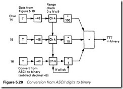
Once in the memory, the data must be converted to numeric form. From Table 5.1, it can be seen that hex 30 (decimal 48) must be subtracted from an ASCII code to give a number. A procedure similar to that in Figure 5.20
must be used (with suitable range checking to prevent garbage being accepted).
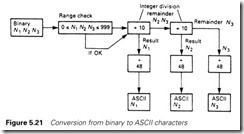
Writing data is similar, except that the ASCII string must be built up inside the PLC. This requires breaking a number down into a byte for each digit as summarized in Figure 5.21. The data are then sent to the buffer with a BTW instruction.
Area networks
Introduction
So far we have considered point to point links. For a true distributed control system we need a method whereby several PLCs or computers can be linked together to allow communication to freely take place between any members of the system.
To achieve this we need to establish a connection topology, some way of sharing the common network that prevents time-wasting contention and an address system that allows messages to be sent from one member to another. Such systems are known as local area networks (LANs) or wide area networks (WANs), depending on the size of the area and the number of stations.
Transmission lines
Any network will be based, to some extent, on cable, and at the high speeds used there are aspects of transmission line theory that need to be considered.
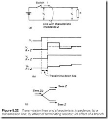
Consider the simple circuit of Figure 5.22. At the instant that the switch closes, the source voltage does not know the value of the load at the far end of the line. The initial current step, i, is therefore determined not by the load, but by the characteristics of the cable (dependent on the inductance and capacitance per unit length). A line has a characteristic impedance, typically 75 W or 50 W for coaxial, and 120–150 W for biaxial or screened twisted pair. The initial current step will therefore be V/Z where Z is the characteristic impedance.
After a finite time, this current step reaches the load R, and produces a voltage step iR. If R is not the same as Z, this voltage step will not be the same as V, and a reflection will result. Typical results are shown in Figure 5.22(b).
This effect occurs on all cables and is normally of no concern as the reflections only persist for a short time. If, however, the propagation delay down the line is similar to the maximum frequency rate of the signal, the reflections can cause problems. It follows that a transmission line should be terminated by a resistance equal to the characteristic impedance of the line. Normally, devices for connecting onto a transmis- sion line have a high input impedance to allow them to tap in anywhere, with terminating resistors being used at the ends of the line.
A side effect of this is that T connections, or spurs, are not allowed (unless the length of the spur is short). In Figure 5.22(c) a T has been formed. To the signal, coming from the left, the two legs appear in parallel, giving an apparent impedance of Z/2 and a reflection.
Network topologies
From the previous section it should be apparent that any network can sensibly only be based on a ring (which needs no terminating resistors) or a line (with a terminating resistor at each end).
Figure 5.23 is a master/slave system where a common master wishes to receive or send data from/to slave devices, but the slaves never wish to talk to each other. All the slaves have addresses, which allows the master to issue commands such as ‘Station 3; give me the value of analog input 4’ or ‘Station 14; your setpoint is 751.2’. Such systems are often based on RS422.
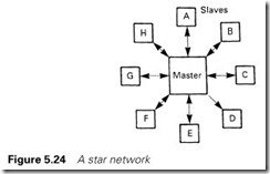
The star network of Figure 5.24 is again based on a master with a point to point link to individual stations. This arrangement is commonly used for high level computer systems. Communication control is performed by the master station. Station to station communication is possible via, and with the co-operation of, the master.
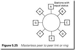
In Figure 5.25 all the stations have been connected in a ring. There is no master, and all stations can talk to any other station and all have equal right of access. The term ‘peer to peer link’ is often used for this arrangement. With Figures 5.23 and 5.24 control was firmly in the hands of the master. With the ring, some technique is needed to avoid
clashes when two stations wish to use the line at the same time. We will discuss this in the following section.
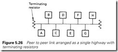
Figure 5.26 is probably the commonest type of network used by PLCs. It is a single line with terminating resistors and, like the ring, is a peer to peer link where all stations have equal standing.
Network sharing
A peer to peer link allows many stations to use the same network. Inevitably two stations will want to communicate at the same time. If no precautions are taken, the result will be chaos. Various methods are used to govern access to the network.
One idea is to allocate time slots into which each station can put its messages. This is known as time division multiplexing, or TDM. Whilst it prevents clashes, it can be inefficient, as a station will have to wait for its time slot even if no other station has a message to send. To some extent a mismatch between the frequency of messages from different stations can be overcome by giving more slots to a hardworking station. With a five-station network and stations labelled A to E, if A has a high workload an order ABACADAEAB, etc. might be adopted. This is sometimes known as statistical TDM.
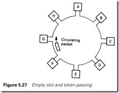
The empty time slot of Figure 5.27 uses a packet which continuously circulates around the ring. When a station wishes to send a message it waits for the empty slot to come round, when it adds its message. In Figure 5.27, station A wishes to send a message to station D. It waits until the empty packet comes round. Then it puts its message onto the network along with the destination address D. Stations B and C pass the message but ignore it because it is not for their address. Station D matches the address and reads the contents (and appends that it has received the message). Stations E–H ignore it, but pass it on. Station A receives the message back again, sees the acknowledgement and removes its message, leading the empty packet circulating the ring again.
A similar idea is a token passing, where a ‘permit to send’ token circulates round the network. A station can only transmit when it is in possession of the token, which is released when the acknowledgement that the message arrived is received.
Both empty slot and token passing require some way of reinstating the packet or token if the network is corrupted by noise or broken. This is usually provided by a master station, or monitor station, but it should be noted this is not fulfilling the same role as the masters in Figures 5.23 and 5.24.
Empty slot and token passing are usually associated with rings, although they can be used with a bus-based system if the stations are arranged as a logical ring.
Bus systems usually employ a method where a station wishing to send a message listens to the network to see if it is in use. If it is, the station waits. If the network is free, the station sends its message (thereby locking out any other station until the message ends). This is known as carrier sense multiple access (CSMA).
Situations can still arise, however, where two stations simultaneously start to send a message, and a collision (and garbage) results.
This situation can easily be detected, and both stations then stop and wait for a random time before trying again. A random time is used to stop the two stations clashing again. This is known as carrier sense multiple access with collision detection (CSMA/CD).
There is a fundamental difference between TDM, empty slot, and token passing as one group, and CSMA. With the former there is a certain amount of time wasting, but every station is guaranteed access within a specified time. With CSMA there is a little time wasting, but a station can, in theory, suffer repeated collisions and never get access at all.
A useful analogy, for which the author is indebted to Allan Roworth of Siemens, is to consider traffic control. TDM/token passing approxi- mates to traffic lights, and CSMA to roundabouts. In heavy traffic the best solution is traffic lights; everyone gets through and the waiting is shared evenly. Roundabouts can ‘lock out’ one road when the traffic flow is heavy and uneven from one direction. In light traffic, however, roundabouts keep the traffic flowing smoothly; and there are few things more annoying than being brought to a halt by a red light, then have nothing go past in the other direction.
A communication hierarchy
Early process control systems tended to be based on a single large com- puter or PLC. The advent of cheap PLCs with good communications has led to the development of a hierarchy of machines which split the
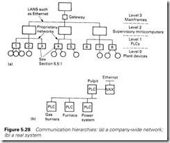
tasks between them. This is generally arranged as in Figure 5.28(a) with a hierarchy split into four levels.
Level 0 is the actual plant, with devices linking to the next level by direct wiring or simple RS232/422 serial links.
Level 1 is the level the majority of this book is concerned with, consisting of PLCs and small computers directly controlling the plant.
Level 2 is microcomputers, such as the DEC VAX, acting as supervisors for large areas of plants.
Level 3 is the large company mainframes, such as IBM’s AS400.
Usually the layout is not as clearcut as Figure 5.28 implies. There are also differences between different companies; some number the layers from top to bottom and some ignore level 0. Normally there will be a split of responsibility in the hierarchy; at the author’s plant, engineering is responsible for levels 0 and 1 and data processing for levels 2 and 3.
There are many advantages to distributed systems. The resulting tree is conceptually simple, and as such is easy to design, commission, maintain and modify.
A correctly designed system will be, for short periods, fault tolerant and can cope in a limited mode with the failure of individual stations.
At the time of writing the author is concerned with the design of a new arc furnace which employs four PLCs and a VAX computer arranged as in Figure 5.28(b). This split allows individual parts to be designed and commissioned separately, and allows the plant to be put into a safe state if any PLC fails or the communications are lost.
A distributed system can also bring about an increase in performance as lower level machines take the work off higher level machines. In Figure 5.28(b), the pulpit PLC issues broad commands to the lower level PLCs, and concerns itself mainly with data gathering for the VAX system. The lower level machines concern themselves with running the plant and monitoring for alarm conditions, passing any information the operator should be aware of back to the pulpit PLC for display on VDU screens.
The ISO/OSI model
Neat as Figure 5.28 is, the interconnection between different machines can bring even more problems than linking two ‘RS232-compatible devices’. Common problems are different baud rates, flow control, routing and protocols.
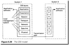
In 1977 the International Standards Organization (ISO) started work on standards to try to ensure compatibility between different manufac- turer’s equipment. This is known as the open systems interconnection (OSI) model, and is primarily concerned with communication between level 2/3 systems in Figure 5.28(a).
It consists of definitions for the seven layers of Figure 5.29. Each layer at the transmission end has a direct relationship with the same layer at the receiving end. The function of each layer is, from the bottom:
1 The physical link layer – concerned with the coding and physical transmission of the message. Requirements such as transmission speed are covered.
2 Data link layer – controls error detection and correction. It ensures integrity within the network and controls access to it by CSMA/CD or token passing.
3 Network layer – performs switching and makes connection between modes.
4 Transport layer – provides error detection and correction for the whole message by ARQ , and controls message flow to prevent overrun at the receiver.
5 Session layer – provides the function to set up, maintain and discon- nect a link, and the methods used to re-establish communication if there are problems with the link.
6 Presentation layer – provides the data in a standard format (which may require the data to be converted from their original form in the initiating application).
7 Application layer – links the user program into the communication process and determines what functions it requires.
As a very rough analogy, consider the placing of a verbal order by tele- phone. This analogy is based on Siemens material published in their brochure ‘Communications Setting the Pace in Automation’.
1 Physical link layer – the phone is lifted and connected to the telephone network. A dialling tone is heard.
2 Error detection and control – it is a good line with no noise.
3 Network layer – the number is dialled, 9 for an outside line and then the number. The phone rings at the other end.
4 Transport layer – the telephone is lifted at the receiving end. ‘This is ACME products, could you hold on please, I’m handling another call. OK, go ahead now. Sorry, I didn’t get that, could you repeat please?’
5 Session layer – ‘This is Aphrodite Glue Works, I have a verbal order for you, number CAP4057, my account number is 7322D.’ The receiver makes a note of these details in case the call is broken prematurely.
6 Presentation layer – ‘I am using order number from the June 1998 catalogue.’
7 Application layer – ‘I require 100 off 302-706 and 50 off 209-417, delivery by datapost.’ ‘OK, 100 off 302-706 and 50 off 209-417 will
be despatched by datapost this afternoon. Total cost £147.20, invoice to follow.’
At any stage, the lower layers can interact. A burst of noise on the line, for example, will cause the transport layer to ask for a repeat of the last message.
It can be seen that layers (1) to (4) are concerned with the communi- cation and layers (5) to (7) are concerned with processing functions for the particular applications.
Proprietary systems
Introduction
The ISO/OSI model is mainly concerned with higher level communica- tions such as linking minicomputers. At the level this book is concerned with, we are primarily interested in linking PLCs. Each manufacturer has tended to have its own standard (Modicon’s MOD-BUS, Texas Instrument’s TIWAY, CEGELEC’s ESP) and these link their own equipment in a straightforward manner. If, in Figure 5.28, PLCs 1, 2 and 3 were Allen Bradley, 4 and 5 were GEM-80s and 6, 7 and 8 were Siemens there would be no real problems in linking similar PLCs. Allen Bradley Data Highway would be used for the first three, CEGELEC’s CORONET for the GEMs, and Siemens SINEC L1 or L2 for units 6, 7 and 8. Each of these is simple to use and, in the author’s experience, very reliable. Linking between the different systems, however, is another story.
In this section we will look at various proprietary systems and at the tentative steps taken to provide standards that allow linking between different manufacturers. All are similar in principle, and provide useful internal diagnostics for fault finding, and less useful green and red communication LEDs on the cards.
For reasons of space we shall consider how machine to machine links are achieved in Allen Bradley, CEGELEC and Siemens PLCs. Each PLC manufacturer has his own proprietary link, some of which are (in no particular order):
· ABB Masternet and Master Fieldbus
· Gould/Modicon Modbus
· General Electric GENET
· Mitsubishi MelsecNET
· Square D SYNET
· Texas Instruments TIWAY
All use similar ideas and are often tantalizingly close; this is a topic that we shall return to in Section 5.5.6.
Allen Bradley Data Highway
PLC-5s communicate with each other on a peer to peer (no master) token passing highway based on twinaxial cable and operating at 57.6 kbaud. Their trade name is Data Highway Plus (an earlier version called Data Highway linked the predecessor of the PLC-5, the PLC-2 range). The PLC station addresses are set on DIP switches on each PLC, and up to 64 stations can exist on one line with octal addresses 0–77.
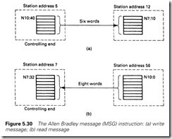
Communication is established with a single message (MSG) instruc- tion. This can be set up to read or write a block of data, the programmer specifying:
(a) the start address at the local end
(b) the start address at the target end
(c) the length of the block to be transferred (in words)
(d) the station address at the remote end
In Figure 5.30(a), station 5 is performing an MSG write, sending six words starting from N10:40 to a block from N7:10 at station 12. In Figure 5.30(b), station 7 is performing a MSG read, taking eight words starting from N10:0 at station 12 and copying them into a block starting at its own N7:32.
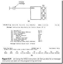
The MSG instruction appears in a program as in Figure 5.31(a), the transfer being initiated every time the rung goes true. The DoNe bit goes true when it has been successfully completed. The ERRor flag goes true when an error occurs. Common errors are a line fault, a non- existent address at the far end, or the PLC at the far end shut down. The cause of the fault is given in flags set in the message control word. Link statistics (e.g. number of retries) are kept in the processor for diagnostic purposes.
The details of the MSG instruction are set up by the programmer via the screen of Figure 5.31(b). These are mostly self-explanatory, with the poss- ible exception of the remote link, which is concerned with sending data via a gateway module to a different highway, possibly of a different type.
The data highway is also used by the programming terminal, so a programmer can connect anywhere onto the data highway and link into any machine on the network.
Allen Bradley have followed the hierarchy of Figure 5.28, and one of their products is the Pyramid Integrator, which combines a PLC-5 (the 5-250) and a MicroVax computer in a single rack, providing a direct (backplane) link between the PLCs data table and the VAX program.
Gem-80 Starnet, ESP and CORONET
The GEM-80 has two forms of inter-machine serial communication. The first, and simplest, method, known as Starnet, provides point to point of master/slave communications (similar to Figure 5.23) with a 20-mA current loop and a protocol known as ESP (extended simple protocol). This only provides master/slave communication, but slave/ slave communication is possible using the master to relay messages.
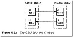
The very flexible GEM data table was discussed in Section 2.3.4. Serial communication uses the J and K tables and the P (preset table). The basic form of the mechanism is shown in Figure 5.32.
Addresses in the K table are used to hold data for serial output, and those in the J table for serial input. The P table is used to set up the presets for the link, such as the baud rate, whether a given machine is a master or slave (GEMs use the term ‘control/tributary’), the size of the blocks to be transferred and whether the transfers free-run continuously or are initiated by the program.
In free-running mode, the operation of the link is totally invisible to the user; data written into K7 in the master machine, for example, will appear, automatically, in J7 in the tributary port with address 0. The actual operation is more flexible than this simple description would imply; in practice, flexible allocation of the data table gives more control and greater speed.
The second form of GEM communication is a masterless peer to peer link called CORONET. This operates on a screened twisted pair cable (RG108AU) at 9.6 K baud to RS485 signal standards. A line length of 4 km is possible with up to 32 stations in the basic form.
The J and K tables hold the Output/Input data and the P table is used to preset each station on the link as before. The link does not free-run, and each transfer has to be initiated by program. This is performed by the I table, to which is written the target address and a send bit to start the transfer. Check bits to say the message has been received are provided in the I table.
Both forms of communication set flags in the F (fault) table, and link statistics showing the number of retries and failed messages are kept.
Siemens SINEC
Siemens PLCs have access to four forms of communication network under the common name SINEC (Siemens Network Architecture for Automation and Engineering). Two of these, prefix L, are low level networks, and two, prefix H, are high level networks.
SINECLI is a master/slave network covering a single master and up to 30 slaves. It operates to RS485 standards on twin twisted pair. The programmer can define the polling order, including repeats as described in Section 5.3.4. The network basically provides master/slave communi- cation, although, like CEGELEC’s Starnet, slave/slave communication is possible by having the master act as a repeater.
SINECL2, known as Fieldbus, is a peer to peer link using token passing. This uses an open architecture, and is a possible candidate for a future standard, as discussed in Section 5.5.6.
SINELECH1 is a baseband network operating at 10 Mbaud on coaxial cable with a maximum length of 2.5 km and implementing the first four layers of the OSI model discussed in Section 5.4. It operates to standard IEEE 802.3, better known as thick-wire Ethernet (see also Section 5.5.5). Up to 1024 stations can be supported, with CSMA/CD being used for access control.
SINELECH2B is a broadband network also operating at 10 Mbaud on coaxial cable. It is based on standards IEE 802.4 and IEE 802.7, conforming to MAP 3.0 (see Section 5.5.6). Access control, as required for MAP, is by token passing. With the data being modulated onto a carrier, the cable can also carry other services such as telephones and closed circuit TV.
Ethernet
Ethernet is a very popular bus-based LAN originated by DEC, Xerox and Intel and commonly used to link the computers at level 2 in Figure 5.28. It uses 50 W coaxial cable, with a maximum cable length of 500 m (although this can be extended with repeaters). Up to 1024 stations can be accommodated, although in practical systems the number is far
lower. Baseband signalling is used with CSMA/CD access control. The raw data rate is 10 Mbaud, giving very fast response at loading levels up to about 20–30% of the theoretical maximum. Beyond this, collisions start to occur.
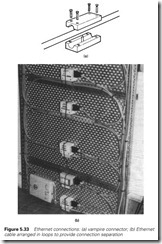
Stations are connected onto the cables by transducers known as nodes on the network. Commonly, ‘vampire technology’ is used for these transceivers, as shown in Figure 5.33(a). The transceiver clamps onto the cable, with a sharp pin piercing the cable and contacting the centre conductor. The arrangement of the pin shrouding prevents it from contacting the screen. This approach allows transceivers to be added, or removed, without disturbing the rest of the network. I must admit to being more than a little apprehensive about vampire technol- ogy, but it does seem to work. To avoid reflections (as discussed in Sec- tion 5.3.2) a minimum spacing of 2.5 m must be maintained between nodes. To assist the user, Ethernet cable has ‘tap-in’ points marked on its sleeving. Where a large number of nodes are to be connected locally, the cabling arrangement of Figure 5.33(b) is used.
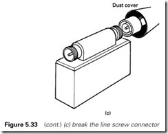
An alternative to the vampire transceivers is the plug-in transceiver using coaxial cable plugs, as in Figure 5.33(c). These are obviously more secure, but have the disadvantage that the network is disrupted if a node is added or removed.
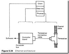
The transceivers are connected to a local controller which performs the access control. Ethernet has three layers, shown in Figure 5.34, which approximate to the functions performed by the same layers in the OSI model discussed in Section 5.4.
Ethernet is possibly the most successful and widely used LAN. Both ABB Masterview and Siemens SINECH1 are essentially Ethernet (although this is not specifically stated as such in their material).
Towards standardization
We have already discussed the difficulties of linking different equip- ment. There are normally few problems in linking PLC networks to higher level computers. PLC manufacturers publish their message for- mat and protocols, and interfacing software (called ‘drivers’) has been written for all common computers and PLCs. The difficulty comes when you want to link two machines at level 1 in Figure 5.28. In many cases, the only economical solution is to do it through the computers and the higher level link.
General Motors (GM) in the USA were faced with this problem and attempted to specify a LAN for industrial control. This was called MAP (Manufacturing Automation Protocol). A similar office-based LAN called TOP (Technical Office Protocol) was conceived at the same time. With GM’s purchasing muscle, it involved several automation equipment
manufacturers. A firm commitment to the OSI model was made, and the network based on broadband token bus as specified in IEEE 802.4 (compare Ethernet; baseband CSMA/CD, to IEEE 802.3). The token bus was chosen as it is deterministic; the response time can be predicted (see discussion on roundabouts and traffic lights in Section 5.3.4).
MAP (currently at version 3.0 at the time of writing) seems to have gone slightly off the rails. The draft title for this chapter was
‘whatever happened to MAP?’. In the course of the research for this book, major PLC manufacturers were visited. Each could interface MAP, but for each (with the exception of Siemens SINECH2B) it seemed to be an expensive add-on which the customer could ‘have if he really wanted’.
There appear to be several reasons for this distinct lack of enthusiasm. The first is a bureaucratic organization and a changing specification. The term ‘moving target’ was used independently on several occasions by different manufacturers. The second reason is cost; MAP links often cost more than the PLC to which they are connected. The expression ‘Designed by big organizations, for big organizations’ was used, and seems apt. The third reason is speed; by using token passing MAP is slow by comparison with Ethernet and the OSI model is not really designed for time-critical applications. The non-deterministic nature of CSMA/CD does not seem to cause any problems up to about 30% of the theoretical maximum loading, and real systems normally operate below 10% loading. The final, and perhaps most crucial, fact is that MAP seems to have settled at a level where it is in direct competition with established LANs such as Ethernet rather than the proprietary systems at level 1 of Figure 5.28.
In the mid-1980s MAP was going to be the common standard of industrial control. MAP systems have been installed, both in Europe and the USA, but it has not yet achieved anything like acceptance.
A typical example of the problems that a fieldbus system may encounter is the introduction of new ideas. All the communications sys- tems described so far are based on what is called the source/destination model. If station A has information for station B, a message is sent with the format:
Source A | Destination B | Data | CRC
If this information is to be sent to several stations, each will need their own message. In applications where multiple setpoints have to be sent to multiple controllers, the delay caused by the time shift between the messages can cause problems, although this can be overcome to some extent by the use of group or global addresses as used by Profibus.
In addition, if station A needs information from station B (the state of an interlock for example), station A must perform a read on each occasion the data is required.
A recent development, called the producer/consumer model, uses a different approach. Here data is placed onto the network with no indication as to who it is for. The format is now simply:
Identifier | Data | CRC
All stations using this data accept it at the same time, eliminating the need for multiple messages. This significantly reduces the number of messages and hence increases the network speed.
The placement of data onto the network can be done in two ways. The first, and fastest, is ‘notify on change’. Here a station only places information on the network when a new value is different to the old. Stations with an interest in this data assume that the status or value remains the same until notified otherwise. There are obvious dangers in this, and a regular pre-defined ‘heartbeat’ (similar in principle to the later Figure 5.37) is included to say a station is active on the network.
The second approach updates on a time basis, each data item having its own, or a global, update time.
At the time of writing, Foundation Fieldbus is the only producer/ consumer fieldbus network, and Rockwell (Allen Bradley) have also adopted the method for their ControlNet. The latter is interesting as it combines the ideas of their remote I/O and Data Highway onto one system and allows PLC racks (and their data) to be shared equally amongst several processors and not dedicated to one as before. There are also European attempts at standardization. In conjunction with the Instrument Society of America, specifications for a low cost (twisted pair) low level network called Fieldbus has emerged. Its full specification was due to be completed by 1992, but (inevitably) has been delayed by commercial and political infighting. It is available (Siemens SINECL2 is one example) and demonstrations linking different manufacturers’ equipment can be seen at most automation and control exhibitions. It could, perhaps, fulfil the role that MAP was publicized for.
Other possible contenders are the, originally German, Profibus described below which is again supported by several companies, and the French FIP. Both of these are similar to, but not identical with, Fieldbus.
Profibus
Profibus is one of the more common fieldbus contenders at present, largely because it has been adopted by Siemens and many other German electrical companies. There are three versions of Profibus designed for three different application areas. All use token passing and are based on the ISO/OSI model.
The first, called Profibus-DP, for Decentralized Periphery, is by far the commonest and is designed to link intelligent masters (e.g. a PLC), to slave devices such as sensors, drives or actuators. Profibus only uses levels 1 and 2 of the ISO/OSI model. Twisted pair RS485 or fibre optics are used for transmission.
The second, Profibus-FMS, for Field Message Specification, is designed for the higher level with multiple masters and allowing peer to peer
communication. Levels 1, 2 and 7 of the ISO/OSI model are used and RS485 or fibre optics for transmission.
Both DP and FMS share the same transmission standards and can consequently work together on the same network.
The final form, designed for Process Automation in hazardous areas, is Profibus-PA which permits the construction of an intrinsically safe network. Profibus-PA uses slightly different standards to DP and FMS, but can be linked by a segment coupler device.
All are linear bus systems, i.e. a straight line. Transmission speeds from 9.6 kbit/s (up to 1200 m) to 12 Mbit/s (up to 100 m) can be used. Screened twisted pair is used, with terminating resistors at each end of the bus. Up to 32 stations can be used in each segment, each with a unique station address. Segments can be coupled with segment repeat- ers, allowing a total of 127 stations to be addressed. Addresses are assigned for global or group data reducing the number of messages and time lag problems when data for several devices are to be changed together.
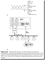
Connections to masters or slaves are made via standard 9-pin D-type connectors, as shown in Figure 5.35(a). Terminating resistors are either switched in internally at the end stations or connected inside the final plugs. Note that the terminating resistors require power, this normally comes from the end stations themselves.
The manufacturer of each device on the network, e.g. a VF drive, provides a disc file, called the GSD, which is a description of the data exchange the device can support (e.g. accepting speed reference and run command and providing load current and drive state, etc.) plus operating parameters such as supported transmission speeds. Included in the GSD file is a unique Identification Number assigned by the Profibus User Organization. The GSD files for all the devices on the network are used along with the station addresses to build a network description which is held in the master.
Because Profibus DP only uses levels 1 and 2, the data exchange maps onto pre-determined areas in the master controller (usually a PLC) as shown in Figure 5.35(b). To change the speed of the drive, the user simply writes the new speed into the mapped area, and the data is trans- ferred with no further action. In a similar manner, slave data and status is automatically read from the mapped area. A Profibus DP network is thus totally transparent to the user.
Safety and practical considerations
Figure 5.36 shows a fairly common situation where a switch connected to one PLC is, via a serial link, causing a motor to run in another. Suppos- ing the motor is started and the link is severed. The bit corresponding to
‘motor run’ which is set inside PLCB will not be cleared by the link fail- ure, and PLCA will be unable to stop the motor.
When the switch is turned off, the serial link control in PLCA will signal an error, but this is of no use to PLCB which does not know that PLCA is trying to communicate with it. This may, or may not, be
a problem, depending on the application, but it is obvious that there are implications that need to be considered.
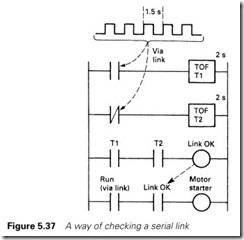
One approach is to define how long an output driven by the link is allowed to be uncontrolled, say 2 s. The originating PLC then sends a toggling signal via the link at a slightly shorter period, say 1.5 s, as in Figure 5.37. Inside PLCB, the true and complement forms of this signal trigger two TOFs (delay off ) set for 2 s. With the link healthy coil ener- gized, the link-driven outputs can be energized. If the link fails, one TOF will de-energize (and one stay energized), causing the ‘link healthy’ signal to de-energize and all link-controlled outputs to go to a safe state. A network introduces extra delays into the system. These delays obviously depend on the loading on the network, but are typically of the order of 0.2–0.5 s on proprietary networks, and a bit slower on
Ethernet and MAP.
Noise is a major source of problems, and normally manifests itself as an increase in the delay time introduced by the network (caused by a large number of retries). Because of checking and CRC discussed earlier, noise rarely causes operational problems, and when it does (in really severe cases) the effect is almost always something not working when requested (rather than something starting unexpectedly). Noise prevents signals getting through; it does not usually cause faulty signals to be accepted.
Obvious precautions against noise are separation from power cables, and the use of conduit or trunking (mainly to identify low-signal-level cables). Cable screens should be continuous and earthed in one, and only one, place. Great care should be taken to prevent screens accidentally grounding inside junction boxes.
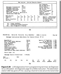
Most proprietary networks have monitoring facilities. Figure 5.38 shows the diagnostics available for the Allen Bradley Data Highway Plus. Some errors are inevitable on all systems (see Figure 5.13) and it is worth logging the rate when a network is first commissioned. This allows checks to be made at a later date, and any deterioration noticed early before problems start to arise.
Fibre optics, discussed in the next section, give almost total freedom from interference.
Fibre optics
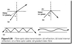
When light passes from one medium to another, the beam is bent as in Figure 5.39(a). This is known as refraction, and is the cause of water appearing shallower than it really is. If the angle of incidence, a, is greater than a certain critical angle qc, the light beam does not emerge from the surface, but is reflected internally as in Figure 5.39(b). This is known as total internal reflection, and it can be shown that
sin qc = 1/m
where m is the refractive index for the two materials.
In Figure 5.39(c), a small-diameter tube of glass has been constructed. Light entering at a shallow angle will be conveyed down the tube with little loss by repetitive total internal reflection. This principle, known as fibre optics, is the basis of an interference-free form of data communication. The principle is very simple. Data at the transmitter are converted into light pulses which are conveyed down the fibre optic cable and detected by a photosensor at the receiver. Fibre optic cable has a very large bandwidth, so modulation or signal multiplexing allows several
high-speed serial channels to be carried down one cable.
There are many advantages to fibre optic cables. The transmission is totally free from problems caused by noise, crosstalk, and ground loops
and gives total isolation between transmitter and receiver. It can also pass through explosive atmospheres with total safety, as a cable breakage cannot result in sparks.
There are two basic types of fibre. Step index fibre operates as in Figure 5.39(c), with reflections occurring at the fibre wall. Graded index fibre has a non-uniform refractive index, causing the light beam to follow a gentler curve as shown in Figure 5.39(d). Graded index fibres have lower losses.
The optical signal is attenuated as it passes down the cable; these losses are usually given in dB/km (typically 5–20 dB/km). Further losses occur at curves (the minimum bending radius is usually related to losses rather than mechanical damage) and at the couplings at each end of the cable. A typical link can operate for 1–2 km without repeaters.
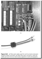
A data transmission cable will usually consist of two fibres (one for each direction) of 200 mm diameter loose inside a protective sheath. Loose sheathing reduces the chance of impact damage. At each end, the sheathing has to be removed, and protective sleeves put onto the individual fibre optic cores as shown in Figure 5.40.
The commonest connector is the SMA connector used in Figure 5.40. This allows fibre optic cables to be disconnected and reconnected like a normal signal cable. Fitting these connectors to the cable is, however, a skilled job. The best method with least subsequent signal attenuation is time consuming, using epoxy resin and a laborious polishing routine. A simpler (and commoner) method uses a crimping tool and specialist cutter. Both require the termination to be checked with a microscope viewing a light source sent down the fibre from the other end.
There are several disadvantages to fibre-optic-based links. The first is that the link is strictly point to point. Topologies such as Ts, multidrops or buses can only be achieved by the use of (expensive) repeaters at each node.
Fibre optic cables are also vulnerable to damage. The cable is not only less robust than conventional cable, but it cannot be easily (or quickly) jointed. With normal coaxial cable, a damaged length can be quite readily cut out and a new length spliced in with through connectors
and little, or no, ill-effects. Through connectors are possible with fibre optic cables, but they introduce high losses into the link and may even prevent it from working. It is not unknown for a new run of cable to be needed, or a repeater introduced, as a result of a single cable break.
Fibre optic cable should always be well protected with conduit or robust trunking to minimize damage. Although there is no technical rea- son why fibre optic links should not share cable tray with 33-kV cables, it is not good practice as they will probably be damaged if any more power cables are added.
A final important point is safety. Most fibre optic links use high-power optical sources, sometimes lasers. Never look down a cable ‘to see if the transmitter is working’. If there is any doubt about cable continuity, disconnect the cable at both ends (taking care to ensure that the right cable has been disconnected in multicable applications) and use low- power incandescent sources for testing. In many cases, anyway, the source used for data transmission is outside the visible range, and cannot be seen. It can still, however, cause damage to the eye.
