Mechanical service techniques
IT TAKES MUCH MORE THAN JUST A GOOD LOGIC CIRCUITRY
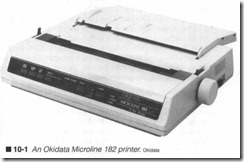
or a pretty enclosme to make a first-class printer. A series of inde pendent mechanical systems are needed to perform the vmiety of physical tasks that every printer must do (figure 10-1). The most obvious mechanism is the paper transport system responsible for moving paper through the p1inter. Every printer made must make provisions to handle paper. Another common mechanism is the cmTiage transport system for moving serial print heads back and forth across the page. Electrophotographic printers and printers using line-print heads do not need a caniage transport. Impact dot-matrix and thermal transfer printers use a media (also known as ink) ribbon that must be handled by a ribbon transport system. Still other printers use “secondary” mechanical systems, such as a paper cutter or sheet stacking mechanjsm.
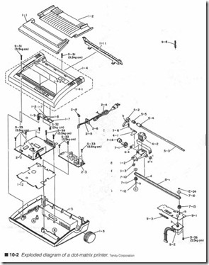
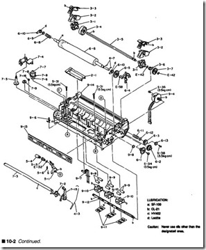
To fully appreciate the importance of a printer’s mechanics, take a look at the exploded diagram of figure 10-2. The ECU and power supply module are in the left side of the illustration (marked 2-2 and 2-3 respectively). The remainder of the drawing shows a de tailed layout of electromechanical and mechanical parts. You have already read about important parts in Chapter 2. This chapter ex pands that background material into a discussion on paper trans ports, carriage transports, and ribbon transports. It also contains an overview of mechanical preventive maintenance.
Friction & tractor paper transports
In order to print anything at all, paper must be moved in front of a print head. Control of the paper must be precise and consistent without inflicting any damage on the paper surface. This is a de manding application, but two types of inexpensive and reliable transport mechanisms have evolved to serve in today’s moving head printers: friction-feed mechanisms and tractor-feed mecha nisms. Both approaches possess their own advantages and disadvantages.
Friction-feed
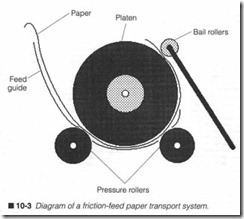
As its name suggests, a friction-feed paper transport uses the force of friction to “push” paper through the printer, as shown in figure 10-3. A single sheet of paper is threaded into the printer along a metal feed guide. The guide ensures that paper is maneu vered properly between the platen and pressure roller(s), then up in front of the print head assembly. A set of small, free-rolling bail rollers press gently against the paper to help keep paper flat while it passes around the platen. To allow the free passage of paper dur ing threading, a lever is often included to separate pressure rollers from the platen (not shown in figure 10-3). Mer paper is posi tioned as desired, the lever can be released to reapply pressure. From then on, paper can only be moved by hand-turning the platen, or during the printer’s actual operation.
Friction-feed paper transports are designed to use single sheets of standard paper. While early implementations demanded that the user manually insert and position each sheet, newer friction-feed designs (such as Hewlett-Packard’s DeskJet series) have modified the mechanics to pick up single sheets from a free-standing stack, similar to the cassette approach used in EP printers. Single-sheet operation eliminates the need to use specialized (i.e., fan-fold per forated) papers, so letterhead and forms can also be used easily.
This combination of factors has made friction-feed systems quite popular.
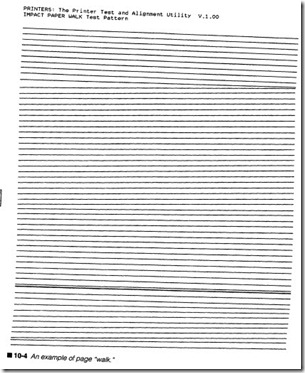
Unfortunately, friction-feed transport systems still have their limi tations in spite of mechanical advances. Probably the most pro nounced and important problem is their tendency to “walk” the page as shown in figure 10-4. For a friction-feed mechanism to work, it must handle each page evenly. If contact pressure is not even, or some obstruction should occur in the paper path, the page will not feed evenly. Although figure 10-4 is rather an ex treme case, it shows you how bad the problem can be. Specially coated papers, heavy-bond papers, and light-bond papers can all contribute to friction-feed problems.
Tractor-feed
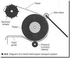
Tractor-feed does not rely on friction to transport paper. Instead, a set of sprocket wheels are mechanically linked to the platen drive train. Pegs on each sprocket wheel mesh perfectly with spe cially made paper. This type of paper (also called tractor orjan fold paper) has holes perforated along both sides. Paper is threaded into the printe r along a metal feed guide. There is very little resistance from its contact rollers, so paper can easily be fed through and secured into its sprocket wheels. Most sprocket
wheels can slide left or right to accommodate a selection of paper widths or tractor feed label products. Bail rollers are included to help keep paper flat against the platen. Once paper is threaded, as shown in figure 10-5, it can only be advanced by hand-turning the platen knob, or in actual printer operation.
You can see the various mechanical components of a tractor feed system in figure 10-2. The frame (marked 9-14) forms the found a tion for the entire mechanical system. A platen (6-6) is driven by the line feed motor (9-4) through a series of gears (marked 6-1, 6- 2, 6-3, 6-5, and 3-7 respectively). You can also locate the tractor feed sprocket wheels (marked 3-1) interconnected by a rod (3-5). This interconnecting rod is very important because the tractor as sembly is driven by only one gear (3-7). Sprocket wheel sheaths and covers (3-2 and 3-3 respectively) keep the fan-fold paper clamped to the wheels.
Although they require a bit of extra mechanical support, tractor feed paper transports are still quite popular because it is virtually impossible to walk or wrinkle a page when it is “pulled” evenly through the printer. The use of fan-fold paper also allows the printer to run for thousands of pages without stopping . This com bination of reliable paper feeding and an almost inexhaustible paper supply make tractor-feed systems the preferred transport mechanism for high-volume business or industrial printing.
One of the main complaints about tractor feeding has been its uni directional nature; you can only pull paper in one direction. How ever, later tractor-feed systems on high-end printers employ a bidirectional sprocket system. A bidirectional sprocket system meshes with perforated paper as it enters the printer and leaves the platen. During normal operation, this bidirectional feed pushes paper inand pulls it out simultaneously. Ifpaper must be reversed, the mechanism will pull paper back evenly without crumpling it.
Driving the paper transport
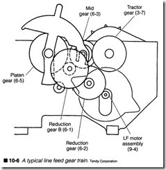
Now that you know the basic mechanical architecture behind fric tion-feed and tractor-feed systems, you can understand how the systems are operated. There are two facets involved in paper transport operation: mechanical and electrical. Both are equally important for proper transport operation. The mechanical paper transport system is illustrated in figure 10-6. While the mechanical
system will vary a bit from model to model, figure 10-6 offers an important glimpse of a tractor-feed gear arrangement. The heart of the mechanism is the paper feed motor (sometimes called the linefeed or LF motor assembly). All of the force needed to move paper comes from this motor; if it fails, so does the paper feed.
The LF motor drives a reduction gear (marked 6-2 in figure 10-2). Force from the first reduction gear is transferred to a second re duction gear (marked 6-1). Together, these reduction gears in crease the effective torque provided by the LF motor. The second reduction gear drives two elements: the platen, and a midgear (marked 6-3). The purpose of the midgear is to adjust speed and torque so that the tractor-feed speed will match the platen speed exactly. If the tractor-feed moves too slowly, paper will “pay out” of the platen too fast and bunch up. If the tractor-feed moves too quickly, it will strain and tear the paper. A midgear also allows the introduction of a clutch mechanism, which allows a user to engage and disengage the tractor gear, thus turning the tractor-feed mechanism on and off at will. When the clutch mechanism disen gages the tractor gear, it also typically engages a pressure roller against the platen (effectively converting a tractor-feed paper transport into a friction-feed transport, and vice versa). As you might imagine, the entire gear train must be intact for the paper transport to function properly. Any damaged or obstructed gears can adversely affect line feeds. A slipping or otherwise damaged clutch (if one is indeed installed) can slow the tractor gear and cause paper to bunch up.
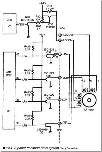
Electrically, the paper transport system revolves around the LF motor, as shown in figure 10-7. The motor itself is a four-phase stepping motor. You can tell by the depiction of each motor wind ing. Pins 2 and 6 represent one winding, pins 6 and 4 are a second winding (pin 6 is common), pins 3 and 5 form the third winding, and pins 5 and 1are the fourth winding (pin 5 is also common). In this design, the common pins are tied to +24 V through Q35, which is enabled when the ‘LFST signal generated by the CPU is logic 1. This configuration allows the CPU to exercise master control over the LF motor. Now, the direction and number of steps produced by the LF motor are determined by signals originating in the ECU. (Figure 10-7 illustrates U3 as the logical element.) However, logic signals alone are not enough to drive the LF motor windings. In stead, each logic signal is “amplified” through a driver transistor (depicted as Q31, Q34, Q36, and Q37). Trouble in the CPU, the gate array, or any of the driver transistors can easily disable the LF motor.
The actual signal characteristics can be viewed with an oscillo scope; you will see a display such as the one shown in figure 10-8. When a driver transistor is fired, the level of e (shown in the up per trace) drops off, and current builds in about 3 ms. When cur rent reaches its peak, the motor winding will exert enough force to step the rotor. When the driver transistor is turned off, its e jumps way up because of the inductive “flyback” produced by the motor, but this voltage spike falls off and settles back to a stable
voltage before the transistor is fired again. The actual duration of an LF motor step is about 3.33 ms.
You can see the relationship between each driver signal in the timing diagram of figure 10-9.
While this diagram might seem daunt ing at first glance, there are several things you should notice. First, the drivers always work in pairs; that is, the LFA driver is always on when the ‘LFA driver is off, and the LFB driver is always on when the ‘LFB driver is off. Second, the LFA and LFB drivers are always separated in time, so the LFA signals will change first, fol lowed closely by the LFB signals, and so on. By sequencing the sig nals in this way, the LF motor is stepped in the advancing direction. If the signal order were reversed, the LF motor would step in the opposite direction.
Paper transport symptoms
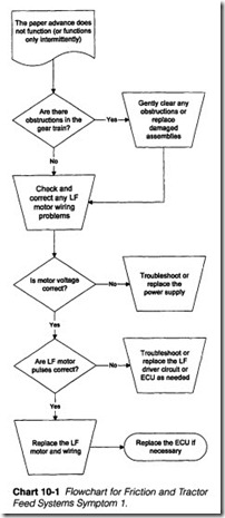
Symptom 1 The paper advance does not function, or functions only intermittently. All other functions check properly. Refer to Chart 10-1. When a paper advance fails to work at all, begin by observing the paper feed drive train assembly. Check any pulleys or gears to ensure that all parts are meshed evenly and are able to move freely. You can watch this by turning the platen knob located out side of the printer. Remove any foreign objects or obstructions that might be jamming the drive train. Never try to force a drive train that does not turn freely! Realign any parts that appear to be slipping or misaligned.
If the gear train is intact, suspect the LF motor and driver system next. Turn off and unplug the printer, then examine the electrical connections for your paper advance motor. Make sure that all con nectors are installed and seated properly. If you suspect a faulty wiring connection, use your multimeter to measure continuity across any suspicious wires. It might be necessary to disconnect the cable from at least one end to prevent false continuity read ings. Replace any faulty wiring.
Warning: The following is a “hot” procedure that must be per formed with the printer on, and with clear access to the ECU and LF motor. Take all precautions to protect yourself from injury.
If you have an oscilloscope, you can check the supply voltage and signals on each side of the driver transistors (as illustrated in fig ure 10-7). You can use the PRINTERS program to generate a se ries of regular line feed sequences for testing. Before you proceed, make sure that +24 Vis available to the motor (you can measure it on motor pins 6 and 5). If +24 V are missing, the motor will not turn, and you should suspect a problem in the +24-V supply, the switching components (i.e., Q30 and Q35), or the CPU or other ECU logic. Once supply voltage is available, check the motor sig nals. If you see logic signals on the base of each transistor, you should find high-energy signals on each collector (similar to the e trace in figure 10-8). If you see a logic signal, but the expected e signal is absent, the corresponding driver transistor is probably defective and should be replaced. If the logic signal is missing to begin with, there is a problem in the ECU. You can replace the logic IC or the entire ECU at your discretion as discussed in Chap ter 9. If +24 Vandall of the e driver signals are reaching the LF motor as expected and the motor still does not turn, the motor is probably defective and should be replaced.
Now if you do not have access to an oscilloscope, or you do not have the time and inclination to follow the “hot” procedure out lined above, you can simply disconnect the LF motor from its PC board and use your multimeter to measure the winding resistance of each motor phase. Figure I0-10 shows you how to do this. Be sure to turn off and unplug the printer before proceeding. Measure across pins 6 and 4, 6 and 2, 5 and 3, and 5 and I.Each measure ment should yield a resistance of about 56 Q (although your par ticular LF motor might have slightly different ratings). Ideally, each phase winding should yield close to the expected resistance. If any of the windings measure unusually high (open) or low (shorted), the motor is likely defective and should be replaced. If the windings all measure correctly, the motor is probably good, and your fault is in the ECU/driver circuitry, which you should sim ply replace outright.
Symptom 2 Paper gathers or bunches up at the tractor-feed sprocket wheels. This is a symptom relatively common to older printers, or printers with a tractor-feed mechanism that was ser viced improperly. The platen and sprocket wheels must transfer paper at exactly the same rate to achieve smooth paper handling. If the sprocket wheels are moving a bit too slow (relative to the platen) for any reason, the paper will eventually “bunch up” at the sprocket wheels.
As shown in figure 10-6, some printers add a clutch assembly that can engage and disengage the tractor-feed unit from the drive train. If there is a clutch mechanism present, see that it is engaged fully and properly. You might want to “pop the clutch” in and out a few times to ensure positive contact. Inspect the drive train gears very carefully, especially the teeth on the tractor gear itself. If one or more teeth are missing, the tractor assembly will “skip” a bit, and might behave quite erratically. Replace any worn or damaged gears. Another possibility is that there might be foreign matter ob structing the gear train. Dust, dirt, debris, or old and hardened lu bricant can cause the tractor gear to skip or stick. Carefully remove any obstruction(s) in the gear train.
Symptom 3 Paper slips or walks around the friction-fed transport. Friction-feed paper transports are only designed to work with cer tain types of paper-brands within a certain range of thickness and weight. Very fme (light bond) paper or very heavy (card stock) paper will probably not advance properly. Slick or other un usual coatings can also upset a friction-feed system. Check the specifications for your particular printer to find its optimum paper type. If you find that you are using an unusual type of paper, try the printer using standard 20-lb. bond xerography-grade paper.
If the problem persists, advance the paper feed knob manually (if possible) and take careful note of each roller condition. An even, consistent paper feed depends on firm roller pressure applied evenly across its entire length. Rollers that are very dirty, or old and dry, might no longer be applying force evenly. Clean and reju venate your rollers with a good-quality rubber cleaning compound available from almost any comprehensive office supply store.
Caution: Rubber cleaning compounds can be dangerous, and might not be compatible with all types of synthetic roller materi als. Read instructions on the chemical container carefully, and fol low all safety and ventilation instructions.
Check your paper path for any debris or obstructions that might be catching part of the paper. A crumpled comer or paper jammed in the paper path or caught in the feed guide can easily interfere with subsequent sheets. Tum off and unplug the printer, and remove all obstructions (being very careful not to mark any of the rollers). A straightened paper clip can often get into spaces that your fmgers and tools will not. Use your needle-nose pliers to put a small hook in the wire’s end for grabbing and pulling the obstruction. Do not disassemble the rollers unless absolutely necessary.
Old rollers might also be out of alignment. Mechanical wear on shafts and bushings (or bearings) can allow some rollers to “float” around in the printer. Carefully examine the condition of each roller shaft. Use the paper loading lever (if available) to separate pressw-e rollers from the platen, then wiggle each shaft by hand. Ideally, each shaft should be fiXed firmly within its assembly, so you should feel little or no “slack.” If you feel or see a roller move within its assembly, replace its bushings, bearing, or shaft. Some pressw-e roller assemblies can be adjusted slightly to alter its con tact force. If yow- particular printer uses nonadj ustable pressure rollers, there is little more to be done other than to replace the me chanical paper feed assembly entirely. If you can adjust roller force (using spring tension or a screw adjustment), do so only as a last resort, and only then in small increments. Careless adjustment can easily worsen the problem. Remember to try cleaning or reju venating the rollers before attempting a mechanical adju stment.
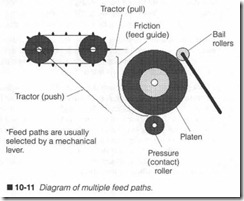
Symptom 4 Paper wrinkles or tears through the printer. Tractor feed paper transport systems are remarkably reliable, so it is very rare to encounter tearing problems using the tractor approach. But many later-model p1inters (especially DMI printers) offer a se lection of paper feed paths, as shown in figure 10-11. A mechani cal lever is typically used to switch between u·actor and friction feed modes. If paper suddenly seems to wrinkle or tear along its perforations during printing, the first thing to check should be the paper feed selector lever.
If your printer’s paper feed mode is set correctly, check the paper path for any debris or obstructions that might be catching the pa per. Fragments of torn paper caught in the feed guide can easily jam the paper path. Carefully remove all obstructions that you might find, but use extreme caution to prevent damage to your rollers or feed guide. Do not disassemble the paper transport un less it is absolutely necessary. If problems persist, you might have to replace the entire mechanical transport assembly.
Carriage transport systems
Impact, ink jet, and many thermal printers use serial print heads. Fully formed text and graphics are formed by passing a print head left and right across a page surface. As the head moves, it places a series of vertical dots that creates the image. In this way, a com plete line of text can be generated in a single pass (letter-quality text or graphics might require additional passes). As you might imagine, the process of moving a serial print head becomes a seri ous concern. It must move at the proper time, at the proper speed, and over the proper distance to within several thousandths of an inch-every pass. The task of moving a serial print head is handled by the carriage transport system.
Carriage transport mechanics
Figure 10-2 presents an exploded view of a typical DMI printer; you can see the individual components of the carriage transport located in the lower middle of the figure. The heart of the carriage system is the carriage transport motor or CR motor (marked 9-2). Signals from the ECU command the stepping motor to rotate clockwise or counterclockwise. As the CR motor turns, it rotates a primary pul ley (7-13) that is attached to a timing belt (marked 8-1). A sec ondary pulley (7-11) keeps the timing belt secure. Although the illustration might not show this clearly, the timing belt and pulleys are notched, much like gears, to prevent the timing belt from slip ping. The carriage platform itself (marked 8-2) attaches to a single point on the timing belt, so as the timing belt spins, it moves the carriage left or right. A carriage is also threaded through a smooth guide rod (7-3). The guide rod acts to stabilize the carriage and keep it parallel to the platen. The print head itself (such as the de vice marked 4-2) mounts to the carriage. As you might imagine, any problems with the CR motor, timing belt, or guide rod will have an adverse effect on carriage motion.
Of course, there are often variations to this configuration. Some times, a pulley system is replaced by a lead-screw type of assem bly. The print head and stepping motor remain unchanged, but the carriage and drive train are modified. A CR stepping motor now drives a gear train that operates a long, coarsely threaded lead screw. This lead screw is threaded into the carriage to become one of its “rails.” The second rail remains a simple, low-friction guide rod that provides stability and support for the carriage (and print head). When the stepping motor turns, it rotates the lead screw (often through a gear train). Clockwise rotation of the lead screw pushes the carriage left, while counterclockwise rotation pulls the carriage right.
For the timing belt and pulley approach, positioning precision is determined by the stepping motor’s resolution and the pulley di ameter. This holds true for a direct drive mechanism. If the pri mary pulley works through a gear train, that gear ratio must also be included. As an example, suppose a stepping motor directly drives a pulley 1 inch in diameter. The circumference of the pri mary pulley would be [1t x d) [3.14 x 1″] 3.14″, so one complete mo tor revolution (thus one complete pulley revolution) would cause the linkage to travel 3.14 inches. If the stepping motor works at 200 steps per revolution, each step would turn the pulley oo of a revolution, or [3.14/200] 0.0157″ of linear travel.
Suppose the pulley was only 0.5 inch in diameter. Its circumfer ence would only be [1t x d) [3.14 x 0.5″] 1.57″, so a single motor ro tation would only move the carriage 1.57 inches. At 200 steps per revolution, each step would drive the carriage [1.57/200] 0.0079″. Smaller pulleys (or motors with more steps per revolution) can achieve fmer positioning, but at the cost of more steps to traverse the platen width.
A similar process holds true for the lead screw drive. For the sake of simplicity, suppose that there is an equal gear ratio, so one mo tor revolution will result in one lead screw rotation. In this case, positioning precision is determined by the spacing (or pitch) of each lead screw thread, as well as stepping motor resolution. If your lead screw has a pitch of one (one thread per one inch of screw length), one motor revolution will move the carriage one inch. At 200 steps per revolution, each motor step will turn the lead screw of a turn, which results in [1″/200] 0.005″ of carriage travel.
If your lead screw has a pitch of 10 (10 threads over 1″ of screw length), 1 thread covers Xo” in length. With 200 steps per revolution, one motor step would still turn the lead screw of a turn, but because a thread now occupies Ylo11 , the carriage would only turn [0.111/200] 0.0005″. The motor would now have to rotate 10 times to achieve a full inch of travel. In practice, lead screws are al most never this fine, but it demonstrates the effects of screw pitch on positioning.
Carriage transport electronics
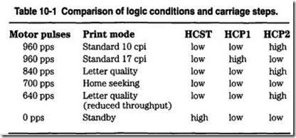
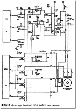
The CR transport electronics are illustrated in figure 10-12. You might notice some similarities between the driver circuitry here, and the design of figure 10-7; the CR circuit uses a four-phase stepping motor, four high-power driver transistors, a master switching circuit to apply voltage to the motor, and logic signals generated from the ECU. However, there are some important dif ferences that you must be aware of. The most noticeable differ ences are in the master motor voltage control circuit operated by the CPU. Rather than a simple on/off switching arrangement as in figure 10-7, the CR driver circuit in figure 10-12 uses a much more extensive circuit to selectively switch power to the CR motor. This approach allows the CR motor to be operated at several different speeds in order to accommodate the printer’s different print modes. Table 10-1 explains the various modes.
There are three logic signals being generated from the CPU. The CPU will select different combinations of these signals depending on the desired carriage speed. For example, when printing in stan dard 10 CPI mode, precise positioning is not required, so the car riage motor can move at a relatively fast 960 pulses per second (pps). To drive the motor at 960 pps, the CPU signals (HCST, HCP1, and HCP2) will be logic 0, logic 0, and logic 1 respectively. As another example, when the carriage is hunting for its “home” position, it will move a bit slower at 700 pps, so HCST, HCP1, and
HCP2 will all be set to logic 0. The logic signals are processed through two comparators (U8) and switched through Q42, Q43, Q44, and Q45. When Q44 and Q45 are off, the CR motor is pow ered through a resistor (R47) and diodes (D3 and D4). The volt age drop across R47 limits the voltage available to the motor, so it can be stepped faster. If either Q44 or Q45 are on, R47 and the cor responding diode are effectively shorted out, so two of the motor windings are then connected directly to 24 V; the motor must be stepped a bit more slowly. When both Q44 and Q45 are on, R47
and both of the diodes are shorted out, and all motor phases are set to maximum voltage, and minimum step rate. An important point to remember is that the actual motor step rate and direction are determined by logic pulses generated at the gate array (U3), not by the amount of motor voltage applied to the windings.
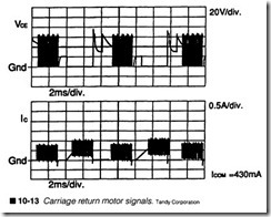
The motor itself is a four-phase stepping motor. You can tell by the depiction of each motor winding. Pins 2 and 6 represent one wind ing, pins 6 and 4 are a second winding (pin 6 is common), pins 3 and 5 form the third winding, and pins 5 and 1are the fourth wind ing (pin 5 is also common). In this design, the “common” pins are tied to +24 V through a diode (D3 and D4) and R47. This configu ration allows the CPU to exercise master control over the CR mo tor and its step speed. Now, the direction and number of steps produced by the CR motor are determined by signals originating in the ECU (flgure 10-12 illustrates U3 as the logical element). How ever, logic signals alone are not enough to drive the CR motor windings. Instead, each logic signal is “amplified” through a driver transistor (depicted as Q38, Q40, Q39, and Q41). Trouble in the CPU, the gate array, or any of the driver transistors can easily dis able the CR motor. The actual motor drive signal characteristics can be viewed with an oscilloscope. By measuring the collector voltage on any one of the phase driver transistors, you will see a display similar to the one shown in flgure 10-13.
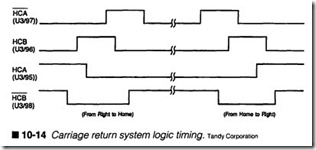
You can see the relationship between each driver signal in the tim ing diagram of figure 10-14. While this diagram might seem daunt ing at first glance, there are several things you should notice. Unlike the logical sequence for an LF system in figure 10-9, the CR logic signals do not work in pairs, but there is a clearly defined se quence in which the signals must be provided; to reverse the mo tor direction, the signal sequence must also be reversed. Second, each of the logical signals are always separated in time, so the ‘HCB signal will change first, followed closely by the HCB signal, then the HCA signal, and the ‘HCA signal. By sequencing the sig nals in this way, the CR motor is stepped counterclockwise, and the carriage is moved left toward its “home” position. If the signal order were reversed, the CR motor would step clockwise, and the carriage would move toward the right.
Carriage transport symptoms
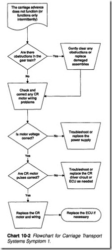
Symptom 1 The carriage advance does not function, or functions only intermittently. All other functions check properly. Refer to Chart 10-2. When a carriage transport fails to work at all, begin by observing the carriage transport drive train assembly. Check the pulleys and timing belt to ensure that all parts are meshed evenly and are able to move freely. With the printer off and unplugged, you can watch this by gently easing the carriage back and forth. Remove any foreign objects or obstructions that might be jamming the motor or drive train. Never try to force a drive train that does not move freely. Realign and tighten any parts that appear to be slipping or misaligned. Replace the timing belt if it has stretched or broken. Also check to see that the carriage is attached securely to the timing belt.
If the drive train is intact, suspect the CR motor and driver system next. Turn off and unplug the printer, then examine the electrical connections for your carriage transport motor. Make sure that all connectors are installed and seated properly. If you suspect a faulty wiring connection, use your multimeter to measure conti nuity across any suspicious wires. It might be necessary to discon nect the cable from at least one end to prevent false continuity readings. Replace any faulty wiring harnesses.
Warning: The following is a “hot” procedure that must be per formed with the printer on, and with clear access to the ECU and LF motor. Take all precautions to protect yourself from injury.If you have an oscilloscope, you can check the supply voltage and signals on each side of the driver transistors (as illustrated in figure 10-12). You can use the PRINTERS program to generate a series of regular carriage return sequences for testing. Before you proceed, make sure that +24 V is available to the motor (you can measure it at the power supply). If +24 Vis missing, the motor will not turn, and you should suspect a problem in the +24-V supply. If voltage is missing at pins 6 and 5 of the motor, either resistor R47 has failed, or diodes D3 and D4 have opened. Once supply voltage is available at the motor, check the motor’s phase signals. If you see logic signals on the base of each driver transistor, you should find high-energy signals on each collector (similar to the e trace in figure 10-14). If you see a logic signal, but the expected e signal is absent, the cor responding driver transistor is probably defective and should be re placed. If the logic signal is missing to begin with, there is a problem in the ECU. You can replace the associated logic IC or the entire ECU at your discretion as discussed in Chapter 9. If +24 V and all of the e driver signals are reaching the CR motor as expected and the motor still does not turn, the motor is probably defective and should be replaced.
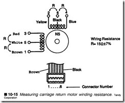
If you do not have access to an oscilloscope, or you do not have the time and inclination to follow the “hot” procedure, you can simply disconnect the CR motor from its PC board and use your multime ter to measure the winding resistance of each motor phase. Figure 10-15 shows you how to do this. Be sure to turn off and unplug the printer before proceeding. Measure across pins 6 and 4, 6 and 2, 5 and 3, and 5 and 1. Each measurement should yield a resistance of about 15Q (although your particular CR motor might have slightly different ratings). Ideally, each phase winding should yield close to the expected resistance. If any of the windings measure unusually high (open) or low (shorted), the CR motor is likely defective and
should be replaced. If the windings all measure correctly, the motor is probably good, and your fault is in the ECU/driver circuitry, which you should simply replace outright.
Symptom 2 Carriage operates, but it does not always position prop erly. The character spacing might be erratic, or the carriage might sometimes slam into side frames. Faulty mechanics are often at the heart of carriage problems. Unplug the printer and inspect the car riage drive train very carefully. Pay particular attention to the tim ing belt and be sure that it is seated properly and reasonably taut around each pulley. A worn or loose timing belt should be reten sioned or replaced. Also check that the carriage assembly is at tached securely to the timing belt; a loose carriage will certainly move erratically. Inspect any drive gears between the CR motor and primary pulley for signs of slipping or broken gear teeth. Re place any parts that appear broken or excessively worn.
If your mechanical system is intact, the trouble is probably electri cal in nature. Start by checking the CR motor wiring. See that any CR motor connectors are attached properly and securely to the ECU. Faulty wiring or loose connectors can easily cause intermit tent carriage operation.
Another possible problem might exist in the positioning feedback system. All moving-carriage printers need to find a “home” position. Often, this is accomplished with an optical sensor or me chanical switch. If the “horne” sensor has failed, the carriage will be unable to position itself accurately. Examine the “horne” sensor as outlined in the procedures of Chapter 9. While many low-end printers simply count motor pulses and approximate the carriage position, some printer designs supplement the “home” sensor with an optical encoder that generates pulses as the CR motor turns. The ECU can count these pulses and compare them with the num ber of pulses sent to the CR motor; if the numbers are equal, the printer knows that the carriage is positioned where it is supposed to be, otherwise, the carriage position can be adjusted “on the fly.” If the optical encoder has failed, the ECU cannot determine if the carriage is where it is supposed to be, and errors in positioning can result. Check the optical position encoder as outlined in the pro cedures of Chapter 9.
Ribbon transport systems
All forms of printing require some sort of media. It is the media that becomes a permanent page image. Each printing technology uses its own particular type of media. For example, impact print ing requires ink from a fabric or plastic ribbon, thermal printing re quires heat-sensitive chemicals already in the paper, or the dry ink in a thermal transfer ribbon, ink jet printing uses a reservoir of liq uid ink, and EP printing takes a supply of toner powder. Media is consumed by the printer during normal operation, so it must be fresh and available at all times. Nowhere is that process more in tricate and troublesome than with ribbons.
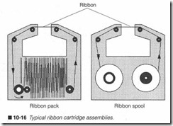
Fabric ribbons are used almost exclusively in impact printers. A fabric ribbon is simply a long, slender length of material saturated with liquid ink, then packed or spooled into a plastic cassette, as shown in figure 10-16. Thermal transfer ribbons use a substrate (foundation) of clear plastic coated with a thin layer of dry plastic ink. Heat from a thermal print head will liquefy the dry ink and transfer corresponding points to the page. They are usually spooled in cartridges, as shown in figure 10-16.
Ribbons must be advanced during the printing process in order to keep fresh media available to the print head at all times. This me chanical operation is handled by a ribbon transport system. Trans ports for ribbon cartridges are often unidirectional; that is, ribbon is advanced in one direction only until it wears out. A typical fab ric ribbon will survive several complete passes before wearing out. Spooled ribbon cartridges are often one-time devices used for
thermal transfer ribbon. When the supply spool is exhausted, a mechanical sensor can be tripped telling the ECU that a new rib bon is needed.
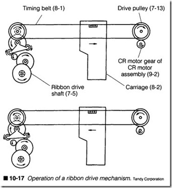
There is no independent motor or solenoid to drive the ribbon transport, so force is “stolen” from the secondary pulley of the car riage transport, as shown in figure 10-17. An intricate “transmis sion” of contact rollers and gears serves to keep the ribbon advancing in the same direction regardless of carriage direction. Rather than explain the drive’s operation in detail, you can easily follow the arrow directions on each roller, but the key to the sys tem is the rocker arm, which swivels based on the secondary pul ley’s direction. Problems with this arm (or any of the drive rollers) will cause severe problems with the ribbon transport. Be aware that ribbon transport mechanisms can vary greatly between print ers, but you can easily recognize a ribbon transport mechanism from the long spindle that inserts into a ribbon cart1idge.
Ribbon transport symptoms
Symptom 1 Print is light or nonexistent. All other functions appear correct. Before you actually begin to troubleshoot a ribbon trans port, examine the ribbon cartridge as the printer operates. If the ribbon drive shaft advances, inspect the ribbon itself; it might sim ply be exhausted. Try replacing the ribbon cartridge and retest the printer. A ribbon cartridge that does not advance might be kinked or jammed within its cartridge. Install a fresh ribbon and retest. If normal operation returns, discard the defective ribbon cartridge.
If the ribbon drive shaft does not turn (or a fresh ribbon does not correct your problem), examine the ribbon transport mechanics, such as shown in figure 10-17. The PRINTERS utility can produce a set of carriage returns that you can use to observe the ribbon transport. Unplug the printer and remove the ribbon cartridge. You will observe the long ribbon drive shaft that inserts into the ribbon cartridge. Grouped just below and behind the drive shaft, you will find a series of other small gears and friction rollers that make up the ribbon transport. The mechanism can be assembled on the carriage or on the printer’s mechanical frame.
Although it is never desirable to operate a printer without its rib bon, it is usually safe to do for limited periods of time, as long as pa per is available to absorb print wire impact or heat. Refer to your owner’s manual for any specific warnings or cautions. You might have to perform some minor disassembly to observe the entire rib bon transport. While the printer is running, watch the ribbon transport mechanism for any parts that might be loose, sticking, or jammed together. Dust and debris might have accumulated to jam the mechanism. Use a clean cotton swab to wipe away any foreign matter. If the transport mechanism is severely worn, it might have to be replaced entirely.
EP mechanical systems
Where moving-carriage printers use relatively straightforward mo tor and gear arrangements to develop motion, the EP printer pro vides a much greater level of mechanical sophistication. Generally speaking, this added complexity is due to the electrophotographic process itself. As you saw in Chapter 4, there are a myriad of op erations that must be executed simultaneously. This part of the chapter examines the EP printer’s mechanical system in detail, and offers some troubleshooting guidance.
The overall mechanical system
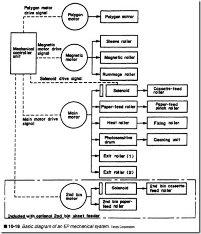
Most EP printers can be broken down into three or four key me chanical areas: the laser scanning system, the development system, the paper transport/image formation system, and (in some models) a supplemental mechanical system for bin feeding (a paper feed modification). The diagram of figure 10-18 gives you some idea of the EP printer’s mechanical complexity. You should note that the mechanical force that drives each of these areas is developed by its own motor, but all motors are operated under di rection of the ECU.
Polygon motor (laser/scanner system)
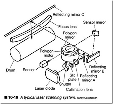
Lasers have proven to be excellent writing mechanisms, but for the laser beam to be of any use, it must be scanned (or swept) across the photosensitive drum in a highly coordinated fashion, as illus trated in figure 10-19. The laser beam is produced by a solid-state laser diode. The beam travels past a mechanical shutter that can be closed as a safety measure to cut off the laser beam whenever the printer’s enclosure is opened. A slit plate helps to narrow the beam, and a collimator lens stops what little divergence there might be, so the diameter of the laser beam will remain constant. The beam then strikes reflecting mirror A, where it is reflected by a rotating polygon mirror to reflecting mirror B. The rotation of the polygon mirror sweeps the beam. The moving beam reflected from mirror B crosses to reflecting mirror C where it is passed through a focus ing/compensating lens, and finally strikes the drum. When the
beam has reached the far end of its sweep, it is reflected to a sensor mirror, which bounces the beam to a laser sensor. This kind of sensor arrangement is used to ensure that the laser is working, and that the mechanical laser system is synchronized properly.
The heart of this mechanical sweeping system is the polygon mo tor. It is the motor that spins a hexagonal polygon mirror. The hexagonal shape basically causes six complete sweeps of the laser beam for every one rotation of the polygon motor; this increases the apparent speed of the scanning system (and thus increases the printer’s throughput). The most important aspect of the poly gon motor is that it maintains a constant speed, so the scanning rate remains constant. If the motor speed varies, even just a little, scan lines can be off significantly, and the resulting image will be extremely distorted.
Magnetic motor (development unit)
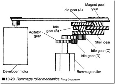
The magnetic motor (figure 10-18), also known as a developer mo tor, is used to drive the three main rollers in an EP development unit: the sleeve roller, the magnetic roller, and a rummage roller. The sleeve roller and magnetic roller are actually integrated into the same “development roller” (also referred to as the transfer roller) assembly located in the toner supply. The magnetic roller at the core of the assembly attracts the iron component of the toner,
while the sleeve roller actually carries the toner into proximity with the EP drum. The sleeve roller receives an electric charge, which is transferred to the toner, as well as an ac bias that helps ensure proper toner transfer to the drum. If mechanical problems arise in the magnetic motor or its gear system, the transfer of toner to paper will be interrupted resulting in light print or erratic toner distribution.
The rurrunage roller is also part of the development system, but it works largely out of sight inside the toner reservoir itself. Over time, toner can clump and become unevenly distributed. The rum mage roller works to keep toner mixed, free, and evenly distrib uted in the cartridge. You can see some of the mechanics for a rummage roller in figure 10-20.
Main motor (paper transport)
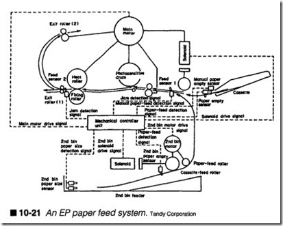
Of all the mechanisms noted in figure 10-18, you might notice that the main motor carries the biggest load in the system. The main motor is basically responsible for driving the entire EP paper transport system: the paper pickup roller, registration rollers, EP drum, fusing rollers, and exit rollers. Figure 10-21 illustrates the entire feed system.
Paper transport begins with a stack of single-sheet paper in the paper cassette. When a paper feed process begins, the main motor
starts, then engages a solenoid that starts a cassette feed roller (also known as the paper pickup roller). The roller grabs a single sheet of paper, and passes it to a set of registration rollers (marked paper feed roller and pinch roller in figure 10-18). The registration rollers will hold the paper in place tmtil the leading edge of the drum’s image is aligned with the top of the page, then the registra tion rollers will feed the sheet into the image formation area. Once the sheet is clear of the cassette, the solenoid disengages and the paper pick-up roller will stop.
Registration rollers continue to feed the page which obtains the image. The page then reaches the fusing assembly consisting of a heat roller and flxing roller (or pressure roller). Heat and pressure melt the toner and squeeze it into the paper rendering a perma nent image. Now the completed page must be ejected from the printer. Ejection is handled by a series of exit roller assemblies. If the page is to be ejected “face up,” it will be passed out of the printer from exit roller 1. If the page is to be ejected “face down,” it will be passed from exit roller 1 to exit roller 2, then out of the printer. Face down is the most common ejection preference be cause this keeps subsequent sheets in order.
To appreciate the complexity of an EP paper transport system, you should have an understanding of the gear arrangements in volved. Figure 10-22 shows the main transmission layout for the paper transport (the three gears that are not highlighted are in-
valved in paper pickup). As you might imagine, any damage or ob structions in the main motor or its transmission will cause notice able problems in paper transport.
Supplemental mechanics {bin feeder)
Finally, figure 10-18 illustrates a second bin motor. This is an op tional assembly and is not available on all printers, but you might en counter similar designs on high-volume paper feed mechanisms. Simply speaking, the second bin feed system is intended to supple ment the low-volume paper cassette. When a second bin is installed (and selected as the paper source), the second bin motor provides the mechanical force for paper pick-up. A solenoid is engaged, which starts a paper pick-up roller (cassette feed roller) to draw a single sheet from the bin supply. The sheet is moved with a paper feed roller in the bin, and passed to the registration rollers. The re mainder of the paper transport process remains the same. It is im portant to note that when a second bin is selected as the paper·· source, the original paper cassette, solenoid, and pick-up system will not be used, so paper is drawn from only one source or the other. You can see the feed path for a second bin feed in figure 10-21. When there is trouble obtaining paper from the second bin, the problem is almost always mechanical in nature.
General mechanical symptoms
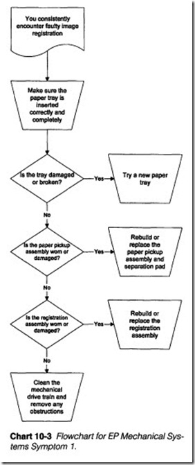
Symptom 1 You consistently encounter faulty image registration. Refer to Chart 10-3. Paper sheets are drawn into the printer by a pick-up roller, and held by a set of registration rollers until a drum image is ready to be transferred to paper. Under normal circum stances, the leading edge of paper will be matched (or registered) precisely with the beginning of a drum image. Poor paper quality, mechanical wear, and paper path obstructions can all contribute to registration problems.
Begin by inspecting your paper and paper tray assembly. Unusual paper weights or specially coated papers might not work properly in your paper transport system (this can also lead to paper jam problems). Ifyou find that your paper is nonstandard, try about 50 sheets of standard 20-lb. bond xerographic-grade paper and retest the printer. Because paper is fed from a central paper tray, any ob structions or damage to the tray can adversely affect page regis tration (or even cause paper jams). Examine your tray carefully. Correct any damage or restrictions that you might find, or replace the entire tray outright.If registration is still incorrect, it usually suggests mechanical wear in your paper feed assembly. Check the pick-up roller assembly first. Look for signs of excessive roller wear. Remove your printer housings to expose the paper transport system. You will have to de feat any housing interlock switches, and perhaps the EP cartridge sensitivity switches.
Warning: This will result in a hot test, so be extremely careful to avoid reaching in or around the printer while the cover interlock is defeated.
Perform a self-test or use the PRINTERS paper feed test and watch paper as it moves through the printer. The paper pick-up roller should grab a page and move it about three inches or more into the printer before registration rollers activate. If the pick-up roller clutch solenoid turns on, but the pick-up roller fails to turn imme diately, your pick-up assembly is worn out. The recommended pro cedure is to simply replace the pick-up assembly, but you might be able to adjust the pick-up roller or clutch tension to somewhat im prove printer performance.
Another conunon problem is wear in the registration roller assem bly. If this set of rollers does not grab the waiting page and pull it through evenly at the proper time, misregistration can also occur. As you observe paper movement, watch the action of your registration rollers. They should engage irrunediately after the pick-up roller stops turning. If the registration clutch solenoid activates, but paper does not move immediately, your registration roller as sembly is worn out. The recommended procedure is to simply re place the registration assembly, but you might be able to adjust torsion spring tensions to somewhat improve printer performance.
Pay particular attention to the components in your drive train as sembly. Dirty or damaged gears can jam or slip. This leads to er ratic paper movement and faulty registration. Clean your drive train gears with a clean, soft cloth, but do not attempt to disas semble the gear train unless it is absolutely necessary. Use a cot ton swab to clean gear teeth and tight spaces. Remove any objects or debris that might block the drive train, and replace any gears that are damaged.
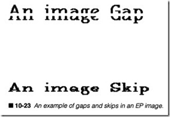
Symptom 2 There are skips or gaps in the page. Images might ap pear similar to figure 10-23. Gaps in the print typically indicate that the page has lurched forward at some point, probably prior to the EP drum. Overlaps (or skips) suggest that instead of lurching forward, the page stalled momentarily. In either case, your prob lem is likely due to a fault in the drive train rather than in a paper transport roller per se. With so many gears at work in the EP printer (e.g., figure 10-22), a broken gear tooth or obstruction can easily cause erratic page transport problems. Turn off and unplug the printer, then examine each gear for signs of damage or ob struction. Make sure every gear meshes properly. Clean the gear train carefully with a lightly dampened cotton swab. If problems persist, try replacing the EP engine assembly.
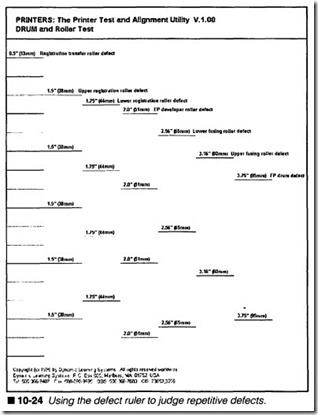
Symptom 3 Print shows regular or repetitive defects. Repetitive defects are problems that occur at regular intervals along a page (as opposed to random defects) and are most often the result of roller problems. Rollers have fixed circumferences, so as paper moves through the printer, any one point on a roller might reach a page several times. For example, if a drum has a circumference (not a diameter) of three inches, any one point on the drum will reach a standard 8.5″ x 1111 page up to three times. If the drum is damaged or marked at that point, those imperfections will repeat regularly in the finished image. As a consequence, it is often easy to identify the fault. The PRINTERS utility provides a drum and roller test ruler to help you check for repetitive defects, as in fig ure 10-24.
Most repetitive defects take place in the EP engine, which con tains the photosensitive drum and developing roller. A typical EP drum has a circumference of about 3.7511 (95 mm). Defects that occur at that interval can often be attributed to a drum defect, typ ically a mark on the photosensitive surface. A developing roller has a circumference of about 211 (51 mm), so problems that repeat every 211 are usually associated with the developing roller. In either case, you can replace the engine and retest the printer.
There are three key registration rollers that can cause repetitive defects. The upper registration roller is typically 1.511 (38 mm) in circumference, while the lower registration roller runs a bit bigger at 1.7511 (44 mm). Trouble at either of these distances suggests a fault in the registration system. The smallest roller is the registra tion transfer roller at 0.511 (13 mm), and a fault there will affect the page as it travels toward the EP drum.
On the other end of the IFS, there are two fusing rollers. The up per fusing roller (the heated roller) has a circumference of about 3.1611 (80 mm). Image marks or defects at that interval suggest a dirty or damaged upper fusion roller. The lower fusing roller runs a bit smaller at 2.5611 (65 mm). Unplug the printer, allow at least 10 minutes for the fusion assembly to cool, then gently clean both fusing rollers, also replace the cleaning pad. If you fmd that the fu sion rollers are physically damaged or are unable to clean them ef fectively, replace the fusing assembly.
Any roller that is fouled with debris or toner particles can con tribute to a repeating pattern of defects. Make sure to examine each of your rollers carefully. Clean or replace any roller that you fmd to be causing marks.
Symptom 4 You consistently encounter paper jam conditions. As figure 10-21 shows, the electrophotographic paper transport sys tem is much more sophisticated than those used in conventional serial or line printers. As a result of this additional complexity, main logic circuitry must be able to detect whether or not paper enters and exits the paper path as expected. As you review figure 10-21, you will notice a series of sensors spaced throughout the paper path. A paper jam condition can often be triggered from sev eral different combinations of conditions:
D Paper does not reach the fusing assembly within a predefmed amount of time.
D Paper does not leave the fusing assembly within a predefined amount of time.
0 Paper reaches the fusing assembly, but fusing roller temperature is below a normal working temperature.
D If paper is exhausted, but the paper sensor arm fails to sense a paper-out condition, the printer will try to pick up a new sheet of paper. Because paper that is not there cannot possibly reach fusing rollers in any amount of time, this too can precipitate a “ghost” jam condition.
Begin by checking paper in the paper tray. If a jam condition is shown but there is no paper, it indicates that your paper sensing lever is not functioning properly. It could be broken, bent, or jammed; otherwise, the sensor itself might have failed. When there is ample paper available, take a moment to be sure that paper is the right size, texture, and weight (bond) for your printer. Un usual or special paper might not be picked up reliably. If you are uncertain as to the correct paper type, remove it and insert a good-quality 20-lb. xerography-grade paper. This type of paper usually has the weight and texture characteristics ideal for EP printing.
When a “paperjam” message is displayed, unplug the printer, open its covers, and make careful note of the paper’s position. Look closely at the leading and lagging paper edges. The problem can often be isolated based on the paper’s jam position. Three main trouble areas are the paper feed area, the registration/transfer area, and the exit area.
Paper feed area
The paper feed area consists of the paper tray (and paper), pick up mechanical assembly, and electromechanical clutch, as shown in figure 10-21. If paper is not reaching your registration rollers, the trouble is probably in this area. Inspect your paper tray care fully. While the tray might seem foolproof, it actually plays an im portant roll in paper feed. If the plastic tray housing is cracked or damaged, replace it with a new tray and retest the printer. Note the movable metal plate in the tray’s bottom. This is a lift mecha nism that keeps paper positioned against the pick-up roller at all times. Remove the tray and paper. Make sure that this plate can move freely; replace your paper tray if it does not. Observe this lift plate as you insert it into the printer. The printer should lift this plate up as the tray is inserted. If this does not happen, repair or replace the printer’s lift mechanism assembly. Add some fresh pa per (50 sheets or so) and gently insert the paper tray. Be sure to insert the tray fully and squarely. If there is any obstruction (or the tray does not seat squarely), find and remove the obstruction.
Next, make sure that your main motor is functioning. Keep in mind that the main motor drives the entire image formation sys tem. If this motor has failed, paper will not be drawn into the printer at all. You can observe the main motor and its gear train as sembly by turning the printer on, opening an access cover, defeat ing the associated interlock switch (if any) and EP cartridge sensitivity switches, then initiating a printer self-test. If the fusing roller temperature is above its lower temperature limit, you should see motor operation immediately. If the main motor fails to oper ate, troubleshoot the motor and its driver voltage. Try a new mo tor. If the problem persists, replace the mechanical controller.
The main motor turns when a print signal is first generated in main logic. It continues turning as long as there is paper in the feed path. However, even though the main motor supplies the force to operate every roller, pick-up and registration rollers are operated only briefly during each print cycle. An electromagnetic clutch (also illustrated in figure 10-21) is used to switch the pick-up roller on and off at desired times. Main logic generates a clutch control signal that is amplified by driver circuits before being fed to the electromagnet. When deactivated, the plunger disengages the pick-up roller from the drive train. When activated, the plunger engages the pick-up roller, which causes the pick-up roller assembly to turn and grab the next available piece of paper. A sep aration pad beneath the pick-up roller prevents more than one sheet from being taken at any one time. Paper stops when it reaches the idle registration rollers. Notice how paper will tend to bow; this is a normal and harmless function in the paper path.
If the main motor operates, but the pick-up roller does not turn (you can observe this during an open-cover test print), inspect the pick-up roller clutch solenoid. Some designs might use two major solenoids: one for the pick-up roller and one for the registration rollers. When printing starts, one of the two solenoids (the pick-up solenoid) should engage immediately. If no solenoid engages, there is an electronic problem, so suspect your mechanical con troller board. If the pick-up solenoid engages, but your pick-up roller does not tum (or turn properly), repair or replace the pick up mechanical assembly. There might be a faulty clutch or other mechanical defect.
When the pick-up solenoid fails to actuate, use your multimeter to measure voltage across the solenoid. You should see voltage toggle on and off as the solenoid is switched. If voltage changes, but the solenoid does not function, replace the solenoid. If voltage re mains at zero (or does not switch from some other voltage), there is probably a fault in the solenoid driver circuit. Troubleshoot the solenoid signal back into main logic, or replace the mechanical controller outright.
Finally, you can check for feed roller wear by measuring the dis tance between the paper’s trailing edge, and the end of the paper tray just as the sheet stops. This time occurs between the point that the pick-up roller stops, and the registration rollers start. Nor mally, this trailing edge should advance about three inches or more. If it does not advance this far, your pick-up roller is probably worn out. Replace the pick-up roller assembly and separation pad.
Registration/transfer area
Registration rollers hold on to the page until its leading edge is aligned with the drum image. Force is supplied by the main motor, but another electromagnetic clutch is typically employed to switch the registration rollers on and off at their appropriate time. Once paper and the drum image are properly aligned, the mechanical controller sends a clutch control signal, which is amplified by driver circuits to operate the registration clutch solenoid. After the clutch is engaged, registration rollers carry the page forward to receive the developed toner image. The registration/transfer as sembly usually consists of registration rollers, the drive train, a registration clutch solenoid, a transfer guide, and the transfer corona assembly. If paper does not reach the fusing rollers, your fault is probably in this area.
You can observe registration-roller operation by opening a hous ing, defeating any corresponding interlocks, and defeating any EP cartridge sensitivity switches, then initiating a self-test. Use ex treme caution to prevent injury from high-voltage or optical radia tion from the writing mechanism, especially lasers. Observe the paper path and drive train very carefully. If you observe an ob struction in the paper path or in the drive train, tum off and un plug the printer before attempting to clear the obstruction. Replace any gears or bushings that appear damaged or worn out. Pay close attention to any tension equalizing springs (called tor sion springs) attached to the registration rollers. Reseat or re place any torsion springs that might be damaged or out of position.
Inspect the monofilament line encircling the transfer corona. Make sure that the line is intact, and not interfering with your paper path. Do not approach the corona with your hands or any metal tool. If you see signs of interference, turn off and unplug the printer, then allow high voltage to discharge for at least 10 minutes before re placing the monofilament line or transfer corona assembly.
If your main motor and drive train operate, but registration rollers do not turn (or they turn improperly), inspect the registration sole noid clutch. It will usually reside adjacent to the pick-up solenoid clutch. The solenoid should engage moments after the pick-up roller disengages. Ifthe registration solenoid does not engage, there is an electrical problem; replace the solenoid or mechanical con troller board. If the solenoid does engage, but registration rollers do not turn, your mechanical clutch or registration rollers are probably worn out. Replace the mechanical registration assembly.
When your registration solenoid fails to actuate, measure the sig nal driving the solenoid. You should see the signal toggle on and off with the solenoid. If the signal changes, but the solenoid does not flre, replace the jammed or defective solenoid. If voltage signal does not change, there is probably a fault in the solenoid driver circuit or mechanical controller board. Replace the solenoid or mechanical controller as required.
Exit area
At this point, a page has been completely developed with a toner powder image. The page must now be compressed between a set of fusing rollers; one provides heat, while the other applies pres sure. Heat melts the toner powder, while roller pressure forces molten toner permanently into the paper fibers. This fiXes the im age. As a fixed page leaves the rollers, it tends to stick to the fu sion roller. A set of evenly spaced separation pawls pry away the finished page, which is delivered to the output tray. A series of exit rollers direct the page to the output as in figure 10-21. Main motor force is delivered to the fusion rollers by a geared drive train. There are no clutches involved in exit area operations, so the drive train moves throughout the entire printing cycle. It is important that the printer detect when paper enters and leaves the exit area. Based on paper size and fusion roller speed, a page has only a set amount of time to enter and leave the exit area before a jam con dition is initiated. To detect the flow of paper, an optoisolator is usually actuated by a weighted plastic lever. You can see these sensors in figure 10-21.
Normally, a paper flag lever protrudes down through a slot in the empty paper path. This leaves the optoisolator clear. Its resulting logic output indicates no paper. When paper reaches the lever, it is pushed up to the paper’s level. This, in turn, moves the flag into the optoisolator slot, causing a logic change that indicates paper is present; a timer is started in main logic. When everything works properly, paper moves through the fusion roller assembly. As pa per passes, the lever falls again, returning the optoisolator to its original logic state. If the optoisolator returns to its initial value be fore the timer expires, it means that paper has moved through the exit area properly. If paper remains, a “paper jam” is indicated. A long-term timer was started at the beginning of the printing cycle. If this long-term timer expires before paper first reaches the paper flag lever, a “paper jam” is also generated. As you might suspect, there are a variety of problems that can precipitate a jam error.
Begin by checking the paper path for any obstructions. Unplug the printer and expose the fusing assembly. It might be necessary to remove secondary safety guards covering the heater roller. Re move any obstructions or debris that you fmd to be interfering with the paper. Make sure that your separation pawls are correctly attached. Clean the pawls if they appear dirty. Inspect the paper flag lever carefully to be sure that it moves freely. Replace the flag lever assembly if it appears damaged or worn out. Also check all interconnecting cables and wiring to see that the paper lever op toisolator is attached.
The drive gears that run your fusion rollers are often attached to a door housing. In this way, fusing rollers are disengaged whenever that access door is opened. This set of gears is sometimes the “de livery coupling” assembly. If these gears are not engaging properly because of wear or damage, the fusion rollers will not operate (or operate only intermittently). Repair or replace any faulty delivery coupling components.
If the mechanics of your exit area appear to be operating correctly, you should examine the operation of the exit sensors. Turn on the printer and use your multimeter to measure voltage across the op toisolator’s output. You might have to defeat any open cover inter locks to ensure proper voltage in the printer. Use extreme caution when measuring, and stay clear of the high-voltage coronas. Move the paper lever to actuate the optoisolator. You should see the out put voltage toggle on and off as the optoisolator is actuated. If out put voltage does not change, replace the faulty optoisolator. If voltage changes as expected, but paper jams are still indicated, troubleshoot your sensor signal back into the mechanical con troller circuit.
Symptom 5 You see an error number or message indicating a polygon motor or “scanner” problem. Keep in mind that a scanner assembly is only needed for EP printers using laser writing mechanisms. LED writing mechanisms do not use scanning mirrors at all. The scanner is an optical-grade hexagonal mirror driven by a small, brushless de motor (an induction motor). Printing will only be enabled after the scanner has reached and maintained its proper operating speed. The scanner is engaged at the beginning of a printing cycle, so the scanner turns as the main motor turns. For many “laser” printers, you will recognize the scanner motor by a somewhat distinctive, variable pitch whirring noise. Motor speed is constantly monitored and controlled by the mechanical controller board. If the motor fails to turn or maintain speed when power is applied, a scanner “error” is generated.
Turn off and unplug the printer, open its housings, and carefully inspect connectors and interconnecting wiring between the poly gon motor and its driver circuits. Reseat any connectors or wiring that appears to be loose. The scanner is usually tested briefly dur ing EP printer initialization. If you cannot hear the scanner motor, replace the entire laser/scanning assembly. A low or missing exci tation voltage indicates a defect in your mechanical controller board that switches its motor voltage on and off. Troubleshoot the excitation voltage and switching circuitry back into the mechani cal controller, or replace the board entirely. Remember that you might have to defeat cover interlocks to enable the printer’s low voltage power supply. Use extreme caution to protect yourself from injury any time the enclosure is opened.
Preventive maintenance
Mechanical parts are often prone to a great deal of wear and tear before a serious breakdown actually occurs. The majority of that wear is caused from the friction produced by ordinary mechanical contact, as well as additional friction generated by debris and dried lubricants inthe drive trains. A routine series of cleaning and lubrication procedures can help to extend the working life of your mechanical parts. You should perform cleaning and lubrication procedures on a regular basis, and whenever your printer needs repair.
Clean the printer
Your printer is going to accumulate dust and debris around its outer case and protective coverings, as well as inside its carriage and paper handling areas. Over time, any accumulation will work its way into just about every mechanism. This can cause such trou bles as sticky gears, slipping belts, or blockage across an optical sensor. A little time spent simply cleaning the printer can yield dividends later on when something really goes wrong.
Clean the outer case and coverings using a soft, clean cloth lightly dampened inwater. Never spray water or cleaner directly onto the case or coverings. If cleaner is needed to remove stubborn marks, apply a little mild household detergent directly to your dampened cloth. Avoid all solvent-based cleaners, which attack the plastic in your covers. Use extra care to prevent wetting the control panel.
Remove the protective coverings from your printer and vacuum away any dust from the carriage and paper handling areas. You can loosen any adhesive materials that remain with a soft-bristled brush. You can buy a small, battery-powered electronic vacuum for this purpose, but any household vacuum with a flexible nozzle should do. While vacuuming, be careful not to change any dip switch settings or dislodge any jumpers. Replace all coverings and retest the printer.
Clean the rollers
Any dust or debris that can find its way into a carriage area can also work into the paper transport area, so it is usually a good idea to clean and rejuvenate your rollers as part of a routine mainte nance regimen. Turn off and unplug your printer, then remove pa per from the paper transport. Simple dust and stains can usually be removed with a soft, damp cloth and a little effort. Dampen the cloth with water only; never use detergents or harsh solvents to clean rollers. As you rub back and forth against the platen, ad vance the platen knob by hand. Continue cleaning the platen through several revolutions to help carry away any dirt that might have worked into adjoining contact or pressure rollers.
For a superior cleaning, use a cleaning solvent designed specifi cally for use on rubber rollers. Many quality stationery stores will carry this type of solvent. Not only will the correct solvent do an excellent cleaning job, but it will rejuvenate the texture and plia bility of the platen and adjacent rollers. This factor is especially important in friction-feed transports where roller contact plays an important part in its operation. Use only high-quality solvents, and follow the particular manufacturer’s directions exactly. Because many printers use a variety of synthetic materials on their rollers, test any specialized solvent on a small area before proceeding with general rejuvenation. Follow all safety and ventilation instruc tions. Never use nonapproved or caustic solvents to clean your rollers.
Clean the print head
Most paper consists of tightly interwoven fibers bonded together by chemicals, temperature, pressure, and time. Whenever paper is rubbed or struck, it liberates a small amotmt of fibers from its sur face. These fibers settle into the carriage area just like any dust pres ent in the open air, but some paper fibers work into the print head. Thermal print heads need almost no maintenance. You can wipe away any accumulations of dirt or dust using a soft, clean, non abrasive cloth dampened lightly in ethyl alcohol. Regular cleanings can help prevent accumulations of debris from lifting the print head and changing its contact pressure against the paper or trans fer ribbon.
Impact print heads are much more subject to problems because paper fibers will usually mix with oils deposited from ribbon ink. This forms a type of sticky “glue” that works its way into the indi vidual print wires and causes them to jam. If you simply wipe the print head’s face whenever you change the ribbon, you can pre vent long-term buildup in the print wires before this “glue” be comes hard and dry. Print wires that are already jammed can be cleaned easily. Gently extend each print wire by hand (if possible) and clean arotmd each wire with a clean cotton swab dipped lightly in ethyl alcohol or light household oil. Use extreme caution, because wires will only extend several millimeters; avoid using ex cessive force when extending a wire. Also be careful not to bend a wire as you work with it. Work the wire in and out, and continue to clean it tmtil it moves freely.
Inkjet print heads pose a slightly different set of problems. An ink jet nozzle will not clog due to paper dust, but the liquid ink in its channels can begin to dry after prolonged exposure to air. Liquid ink is usually manufactured with a chemical solvent base that does not readily evaporate in air. Ink at each nozzle can often remain exposed to the open air for several days without danger of clog ging. The “home” position of many ink jet printers offers a cap or sponge that helps prevent drying during periods of disuse, but ag ing printers will not “cap” the nozzles very well.
A replaceable ink jet cartridge is very easy to clean. Unclip the car tridge from its holder and clean the nozzles with a cotton swab or clean, soft cloth. In order to prime the cartridge, use the swab’s wooden end to press gently on the ink bladder. Use enough force to form ink beads on each nozzle, but be very careful not to punc ture the bladder. Repeat this several times until the head is clear. Replace the cartridge if the clogged nozzle does not clear.
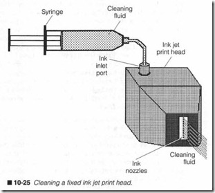
Nonreplaceab le ink jet heads are much more troublesome to clean. A.. cleaning solvent must be injected into the print head to dislodge a clog. The cleaning kit often supplied with many nome placeable head printers offers a syringe and a container of clean ing solvent. Fill the syringe with cleaner and attach it to the head’s ink inlet. Gently force cleaner into the head, as shown in figure 10-25. Solvents reduce the ink’s viscosity and it should flow easily from the nozzles. Continue injecting cleaner until all ink has been evacuated and only clear solvent flows. You might have to let the cleaner sit for a time to dissolve any stubborn clogs. Once the noz zles are cleared, reattach the ink supply and prime the head with ink until all solvent is displaced and ink beads at each nozzle. This is a very messy procedure. Wear old clothing, rubber gloves, and have towels handy.
Clean & lubricate the paper transport
Dust and debris in your paper transport rollers and drive train can cause gears to jam or bind. It could also force rollers out of align ment. The best defense against this is regular cleaning and lubri cation of the drive train. Expose the paper transport drive train. You might have to remove covers or guards that might be protect ing the assembly. Clean the gear assembly carefully with a clean, soft cloth lightly dampened with water and mild household deter gent. Harsh solvents or cleaners can destroy plastic gears and fit tings found in many printers. Use a cotton swab to remove debris from between gear teeth. If you must disassemble a gear train to clean severe jams or realign the assembly, be certain to make very careful notes of how each part goes together.
Reapply lubricants to the drive train only if they were lubricated to begin with. Ideally, you should use the same type of lubricant, but a light household oil is usually acceptable. Place a few drops onto the teeth of one or two gears, then turn the platen knob to distrib ute that oil throughout the drive train. Continue adding and dis tributing oil until all gear teeth show a light but consistent coating. Never apply oil to wires or belts in a pulley system. Avoid heavy oils and grease; these simply attract dust and debris that will be even harder to clean the next time around.
Clean & lubricate the head transport
For proper operation, a carriage must be able to ride freely on its guide rail(s) at all times. Through a combination of humidity, dust, and dirt, rust can emerge along steel rails (stainless steel rails are sometimes used, but these are expensive), but plastic is fre quently used as a substitute. Rust causes a dramatic increase in friction between the rails and carriage. This can slow the carriage down and cause rough positioning. In extreme cases, it can actu ally bind the carriage.
Turn off and unplug the printer and wipe your guide rails with a clean, soft cloth to remove any loose dust or rust particles. Most other rust can be swept away with a light touch of steel wool. Use caution when removing rust. Steel wool fibers and rust particles are conductive, so keep your electronic circuits covered and be sure to vacuum any rust or wool that might have been shed. Place a few drops of light household oil onto each rail, then move the carriage back and forth to distribute oil evenly. A light coat of oil will reduce friction, and help protect rails from further rust. Never use heavy oils or grease to lubricate rails.
