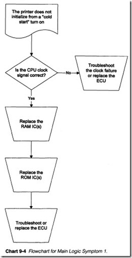
Electronic service techniques
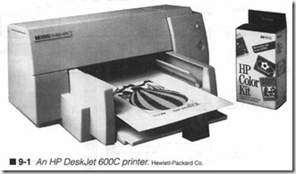
REGARDLESS OF THE PARTICULAR TECHNOLOGY AT WORK in your printer (figure 9-1), each and every operation is controlled by a set of electronic circuits that is commonly called the Elec tronic Control Unit (or ECU). The specific architecture and com ponents used inan ECU vary radically between printer models and manuf acturers. A straightforward dot-matrix impact printer might only need simple control circuits, while a sophisticated EP printer requires a much more complicated ECU. This chapter shows you the internal workings of an ECU, and presents a series of troubleshooting procedures.
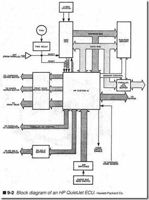
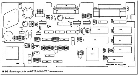
Regardless of their complexity, all ECUs must be capable of per forming the same range of tasks . They must communicat e with the outside world (i.e., the user as well as the computer), and trans late communicated data and control codes, often in the ASCII for mat, into characters or patterns of dots that can be used to drive a print head. An ECU also directs such physical tasks as carriage transport and paper advance. It interprets sensor information re garding paper supply, carriage position, and head temperature. Fi nally, each of these tasks (and more) must be coordinated to work together. A typical ECU can be broken down into six functional ar eas: communication (or the interface), memory, control panel, drivers, main logic, and sensors. Figure 9-2 is an actual block dia gram for a Hewlett-Packard QuietJet series printer. The circuit board layout for this block diagram is implemented in figure 9-3. Notice that these areas can often be fabricated onto a single PC board. Each of the major areas of an ECU are represented here. Before you begin troubleshooting an ECU, you should thoroughly understand the operations and key components of these sections.
Communication
By itself, the printer serves little practical purpose. To be of any use at all, the printer must conununicate with the outside world to receive the characters or graphics data that it must print. Binary data representing this information is sent from the host computer to your printer over one of several possible communication links. The computer also receives commands and status information back from the printer. These return signals are used to regulate the flow of data. Although there are many variations of communi cation links, data is transferred using either a serial or parallel technique. Data is sent over a parallel link as whole characters; that is, all the binary digits (or bits) that compose a character are sent at the same time over multiple signal wires. A serial link trans fers data one bit at a time over a single wire. This part of this chap ter explains the important concepts of printer communication.
A computer typically sends three types of information to a printer: text characters, control codes, and graphics data. Not all printers will accept character or graphic data or interpret them in the same way. Character data simply represents text, letters (in any lan guage), numbers, punctuation, or other text symbols. Graphics data are the individual dots (or sequences of dots) that compose a much larger graphic image. Control codes are used to send com mands to the printer. They can set general operating modes such as font style, enhancements, or pitch, but they can also direct im mediate operations, such as form feed or line feed. Using control codes eliminates the need to operate a control panel manually while a document prints. Other control codes can switch the printer into and out of various graphics modes. When a printer is placed in a graphics mode, subsequent information sent to the printer will be processed as individual dots before being sent along to the print head or writing mechanism. An opposing control code, or reset control, will return the printer to its character (or text) mode. Printing under Windows or Windows 95 is done exclusively in the graphics mode.
ASCII explained (text characters)
Before any communication can take place, both the printer and the computer must speak the same language; when a computer sends out the character “H,” its printer must be able to recognize that character as an “H.” Otherwise, it will just print unintelligible garbage. Because each character and control instruction is repre sented by its own unique numerical code, both printers and com puters must use a common set of codes that describe some minimum number of characters. In the early days of computers, each manufacturer had their own character code set. You can prob ably imagine how difficult it was to combine equipment made by dif ferent manufacturers. As the electronics industry matured and printers became more commonplace, the demand for equipment compatibility forced manufacturers to accept a standard character code set.
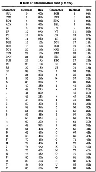
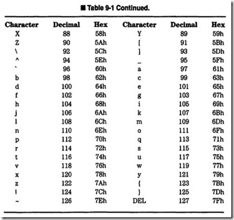
The American Standard Code for Information Interchange (known as ASCII) has come to represent a single, standard code set for computer/printer communication. Table 9-1 represents a conven tional ASCII table showing characters, their code numbers, and a binary representation of those numbers. The standard ASCII code covers letters (upper- and lowercase), numbers, simple symbols for punctuation and math functions, and a few basic control codes. For example, if you want to print a capitol “D,” your computer must send the number “68” to the printer. The printer would then translate “68” into a dot pattern that reflects the selected font, character pitch, and enhancements, to form the letter “D.” To print the word “Hello,” a computer would have to send a series of numbers: “72,” “101,” “108,” “108,” and “111.” Pure (original) ASCII uses codes 0 to 127.
Due to the way character codes are actually sent, however, most computers can also use ASCII codes ranging from 128 to 255, but keep in mind that any code over 127 is not pure ASCII. Instead, codes from 127 to 255 are sometimes called an alternate charac ter set. Such an alternate character set can contain single block graphic characters, Greek symbols, or other language characters. In some cases, codes 128 to 255 just duplicate codes 0 to 127. If your computer sends a code from 128 to 255, you might be print ing characters that are different than those on your computer screen.
Control codes (the great ESC)
Not only must a computer specify what to print, it must also spec ify how to print. Carriage returns, line feeds, font styles, and en hancements are just some of the controls that a computer must exercise to automate the printing process. Just imagine the confusion if you stand by your printer to change these modes manually while a document was printing! Unfortunately, control codes are often the cause of some incompatibilities between computers and printers. When ASCII was first developed, printers were extremely primitive by today’s standards. Multiple fonts and type sizes, graphics, and letter-quality print had not even been considered. Few controls were needed to operate these early printers, so only those few critical controls were incorporated into ASCIT. You might recognize such controls as Form Feed (FF), Line Feed (LF), or Carriage Return (CR) from Table 9-1.
With the inclusion of advanced electronic circuitry, a greater amount of “intelligence” became available in printers. This, in turn, has made so many of their current features possible. ASCII codes are still standard, but there simply are not enough unused codes to handle the wide variety of commands that are needed. Manufacturers faced the choice of replacing ASCII (and obsoleting an established and growing customer base), or developing a new scheme to deal with advanced control functions. Ultimately, man ufacturers responded to this by devising a series of multicode con trol sequences. These were known as escape sequences because the ASCII code “27” (Escape) is used as a prefix. Printer capabili ties can vary greatly between models and manufacturers. As a re sult, escape codes are not standard. If computer software is not written or configured properly for its particular printer, control codes sent by the computer might cause erratic or unwanted printer operation.
Escape sequences are typically two or three ASCII codes long, and each begins with ASCII code “27.” It is the escape character that tells the printer to accept subsequent characters as part of a con trol code. For example, to set a printer to “Compressed Print,” a computer might have to send an ASCII code “27,” followed by an ASCII code “15” (SI). Software in the printer’s main logic would in terpret this code sequence and alter the appropriate modes of op eration accordingly. A typical sequence to set a new “Character Pitch” might be “27” (Escape), followed by a “103” Oetter “g”). Multicode sequences will certainly become more conunon as print ers get even more sophisticated. The PRINTERS utility allows you to test printer features by entering manual escape code sequences.
Number systems
Not only must a computer and printer exchange codes that they both understand, but every code must be sent using a number sys tem that is compatible with electronic (digital) circuitry. You al ready know the decimal (or base 10) number system. The symbols 0 through 9 are used in combinations that can express any quan tity. The symbols themselves are irrelevant; ten other symbols could just as easily have been used, but 0 through 9 are the ones we have accepted down through the centuries. What is important is the quantity of characters in a number system. In decimal, one character can express 10 unique levels or magnitudes (0-9). When the magnitude to be expressed exceeds the capacity of a single character, the number carries over into a higher represen tative place, which is equal to the base of the system raised to the power of that place. For example, the number 276 has a 2 in the “hundreds” place, a 7 in the “tens” place, and a 6 in the “ones” place. You have worked with this system since granunar school.
If electronic circuits could recognize ten different levels for a sin gle digit, then digital electronics would be directly compatible with our human decimal system, and ASCII codes would be exchanged directly in their decimal form. However, digital electronics can only recognize two signal levels. These conditions are On or Off (True or False). This is known as the binary (or base 2) number system. Because only two conditions can be expressed, only two symbols are needed to represent them. The symbols “0” (Off) and “1” (On) have come to represent the two possible conditions for a binary digit (commonly called a bit). ASCIT codes must be sent as sets of binary digits.
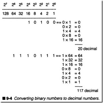
As with the decimal number system, when a quantity to be ex pressed exceeds the capacity of a character (in this case it is a “1”), the number carries over into a higher place that is equal to the base of the system (base 2) raised to the power of the place. You have probably seen binary signals expressed as 2n, where n is the bit’s place position. As figure 9-4 illustrates, the decimal num ber “20” equals the binary number “10100.” A lowercase “u” with an ASCII code of “117” would be expressed as “1110101” in a dig ital system. Seven bits can express numbers from 0 to 127. Eight bits can express numbers up to 255.
Binary digits
In order to have any meaning at all in electronic circuits, there must be a clearly defined relationship between a binary digit and a voltage level. Because a binary “1” is considered to be an On con dition, it usually indicates the presence of a voltage. A binary “0” is considered Off, so it denotes the absence of a voltage. In reality, the actual amount of voltage that describes a 1or 0 depends on the logic family in use. Conunon digital circuits using conventional TTL (Transistor-Transistor Logic) ICs classify a 0 as 0 to +0.8 Vdc, and a 1as +2.4 to +Vee (the voltage powering the IC).
Practical printer communication
There are literally hundreds of ways that you might be able to im plement a communication interface. A great many versions have been tried and abandoned since the early days of conunercial printers. The evolution of technology favors the best methods and techniques, so those that work well and grow with advances in technology can sometimes develop into standards that other man ufacturers adopt in the future. Standards are basically a detailed set of rules and performance characteristics that clearly define the construction, connection, and operation of a circuit or system, in this case a communication interface. By adopting an established standard, manufacturers can be sure that printer brand “Y” will operate just fine with computer brand “X,” and vice versa. This book covers two types of interfaces: parallel (Centronics) and se rial (RS232).
The parallel interface
The Centronics Corporation was one of the original printer manu facturers, so they were able to establish an early lead in the marketplace. Their printers used a parallel interface of their own design. Its speed and simplicity soon made it a “defacto” standard for other manufacturers to duplicate. It is conunonly called the Centronics interface, although most PC technicians simply refer to it as the parallel port or LPT port.
Parallel architecture
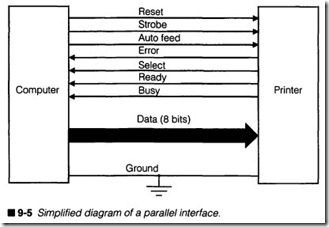
A parallel port is easiest to understand because of its straightfor ward operation. You can see a simplified diagram of a parallel in terface shown in figure 9-5. Notice that eight bits of an ASCII code are transferred simultaneously (DO through D7). Data lines alone, however, are not enough to transfer information successfully. Both the computer and printer must be synchronized so that the printer will accept data when it is offered, or ask the computer to wait un til it is ready. Synchronization of a parallel link is accomplished us ing several control wires, in addition to data lines. Some control lines signal the printer, and others will signal the computer.
This mutual coordination is known as handshaking.
Parallel operation is really quite fast. The printer will accept infor mation as fast as the computer can send it, often operating at
speeds exceeding 1,000 CPS. At eight bits per character, that amounts to more than 8,000 bits per second. As discussed later in this chapter, the printer’s internal data bus is also eight bits, so an eight-bit parallel word can be accepted into a data buffer with very little additional circuitry; parallel communication circuits are usu ally very simple. The main disadvantage to parallel links is its lim ited cable distance. With so many high-speed data signals running together in the same cable, its effective length is just a few feet. Beyond that, electrical noise and losses can cause distortion and loss of parallel data.
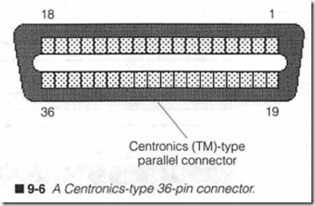
A Centronics-type interface connects a 25-pin subminiature D type connector at your computer to a 36-pin Centronics-type con nector at your printer. The size and shape of this 36-pin connector is standard (Amphenol Corporation #57-30360), so anytime you find a Centronics-type connector, as shown in figure 9-6, you will know the printer supports parallel communication. You might wonder why a 25-pin connector is used at the PC, while a 36-pin connector is used at the printer; what happens to the extra 11 pins? Well, the extra pins on the 36-pin connector are not used, or they are simply tied to ground.
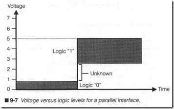
A Centronics-type interface uses standard TTL levels to transfer information, so a binary “0” will be between 0 and +0.8 Vdc, and a binary “1” will be between +2.4 Vdc and +Vee· These logic levels can easily be measured with a multimeter, but a logic probe or os cilloscope would probably be needed to observe actual data occurring on each signal line. Figure 9-7 illustrates the relationship between voltage and logic levels.
Interface signaling
The interface wiring for a typical Centronics interface is illustrated in figure 9-8. As you look at each of the pins along the left (con nector) side of the diagram, you will see that all 36 pins of the Cen tronics interface are accounted for. Another thing you might notice is that the parallel interface is remarkably simple; there is little more there than pull-up resistors and signal conditioning cir cuitry. In fact, each of the pins on the right (internal) side of the diagram are connected to a single gate array IC (an ASIC), which handles all of the parallel communication processing. (The gate array is not shown in the schematic segment of figure 9-8.) Aside from the gate array and signal conditioning components, there is little else that can fail in the parallel interface.
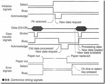
When the printer is no longer bu sy, it generates a b1ief logic 0 P_XACK (acknowledge) signal, which requests a new character from the host computer. This process repeats approximately every 1 ms until all computer data has been sent. Printing must stop if paper becomes exhausted, so the P_PE (paper empty) signal will become logic 0 when paper is used up. This deselects the printer automatically, so you will have to press the “on-line” button tore select the printer after paper is restored. Figure 9-9 shows a typi cal timing chart for a normal printing cycle.
When the interface is first turned on, the P_SLCT (select) signal becomes a logic 1 to indicate that the printer has been selected. P_SLCT will remain logic 1 as long as paper is available and the printer is left on-line (it can be taken off-line through the control panel). The computer sends data bits representing a character or control code simultaneously over data lines P_DATAl through P_DATA8. Once data bits are sent, the computer generates a brief logic 0 on its P_XSTROBE (strobe) line. A P_XSTROBE pulse tells the printer that data is valid, and that it should be accepted and stored in the data buffer memory. Once data is accepted by the printer, it generates a logic 1P_BUSY (busy) signal. The host com puter stops sending information until the P_BUSY signal returns to logic 0.
IEEE 1284
By the end of the 1980s, it was becoming clear that “conven tional” bidirectional parallel ports were simply not adequate to handle the new generations of faster peripherals that were ap pealing for the parallel port (i.e., CD-ROMs, tape drives, and laser printers) . The 150KB/s parallel transfer rates that were once con sidered speedy were now severely limiting the new peripherals. In 1991, a group of major PC manufacturers (including IBM, Lex mark, and Texas Instruments) formed the Network Printing Al-liance (NPA) in an attempt to develop a new parallel port archi tecture. In 1994, the IEEE (in conjunction with the NPA) re leased the Standard Signaling Method for a Bidirectional Parallel Peripheral Interface, also known as IEEE standard 1284. You will encounter this standard when installing new motherboards, multi-I/O boards, and parallel port devices.
The IEEE 1284 does not define a single parallel approach, but in stead outlines five different operational modes for the parallel port: compatibility mode, nibble mode, byte mode, ECP mode, and EPP mode. All five modes offer some amount of bidirectional capability (known under IEEE 1284 as back channel communication). When the 1284-coinpliant parallel port is initialized, it checks to see which operating mode is appropriate.
Compatibility mode
IEEE 1284 is fully backward-compatible with conventional parallel port technologies where data is sent along eight data lines, the sta tus lines are checked for errors and to see that the device is not busy, then a Strobe signal is generated to ”push” the data into the device. As with ordinary parallel ports, the output of a single byte requires at least four I/0 instructions. Data bandwidth is limited to 150KB/s.
Nibble mode
The nibble mode (four bits at a time) is a simple means of receiv ing data back from a peripheral device in fewer I/0 instructions, though it is very inefficient. When used by itself, the nibble mode is limited to about 50KB/s. In most practical implementations of IEEE 1284, the nibble mode will rarely be used for more than gath ering brief diagnostic or status information about the peripheral.
Byte mode
The byte mode allows the PC to disable the hardware drivers nor mally used to operate parallel data lines, which allows the data lines to be used as an input port to the PC. When inthe byte mode, a peripheral can send a full byte to the PC in only one I/0 cycle. Thus, it is possible to acquire data from a peripheral much faster than would be possible in the nibble mode.
ECPmode
The Enhanced Capabilities Port (ECP) allows bidirectional data transfer within a single 110 cycle. When a transfer is requested, the port’s hardware will automatically perform all of the port synchro nization and handshaking operations formally handled by soft ware-driven 110 cycles in the compatibility mode. When properly implemented, an ECP port can nm from BOOKB/s to 2MB/s de pending on the device at the port and the cable between them.
EPPmode
The Enhanced Parallel Port (EPP) is the apex of IEEE standard 1284. Like the ECP mode, EPP operation facilitates bidirectional data transfer in a single 110 cycle with the port hardware itself handling all synchronization and handshaking. EPP operation also can nm from 800KB/s to 2MB/s. However, EPP operation takes an other step forward by treating the parallel port as an extension of the system bus; this allows multiple EPP devices to exist on the same port.
The cable
Conventional parallel ports are limited to cable lengths of about ten feet. Beyond that, crosstalk in the parallel cable can result in data errors. Ideally, high-quality, well-shielded cable assemblies can extend that range even more, but the cheap, mass-produced cable assemblies that you often find in stores are rarely suited to support communication over more than six feet. To support the high-speed communication promised by IEEE 1284, a new cable specification also had to be devised. This is hardly a trivial con cern, especially considering that IEEE 1284 seeks to extend paral lel port operation to as much as 30 feet (about 10 meters).
IEEE 1284 considerations
Unfortunately, while the potential and promise of IEEE 1284 of fers a lot of appeal, there are some serious considerations involved in configuring an enhanced port arrangement. Specifically, you will require an IEEE 1284-compliant parallel port, cable, and pe ripheral (i.e., printer, tape drive, hard drive, and so on) to take full advantage of enhanced capabilities.
Installing an IEEE 1284 parallel port is certainly not a problem; most current multi-I/O boards and late-model motherboards are now providing IEEE 1284 ports. The trouble is that using a $5 printer cable with your old Panasonic KX-P1124 dot-matrix printer will just not provide any advantages. To start benefiting from an IEEE 1284 port, you will need at least an IEEE 1284 cable and a device with significant memory capacity (such as a laser printer). At that point, you might start to see some speed im provements, but the additional speed will still fall far short of the projected figures. illtimately, you will need to install IEEE 1284- compliant peripherals that will provide ID information to the port and allow optimum performance.
The serial interface
A serial approach emerged when the Electronics Industry Associ ation (EIA) developed a comprehensive serial standard that they dubbed “Recommended Standard 232,” or simply RS232 as we know it today. Since its original inception, the RS232 standard has been updated and revised a number of times. For the purpose of this discussion, however, it will simply be called RS232. You should know that RS232 was not designed just for use in printers, but as a universal interface scheme for any serial device, such as a mo dem, video monitor, or keyboard. As a comprehensive standard, it offers many handshaking and signal lines, only a few of which are really needed for printer communication. When RS232 was first introduced, many manufacturers chose to use only the signal lines that they thought were necessary for serial operation. This quickly fragmented the use of RS232, and created incompatibilities be tween computers and printers. Today, the use of RS232 signal and handshaking lines is much more readily accepted.
Serial architecture
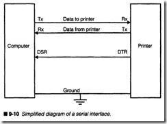
A serial link might appear simpler because of the reduced wiring, as shown in figure 9-10, but its actual operation is somewhat more in volved. You can see from figure 9-10 that two wires are used to transfer information. One of these wires carries data from com puter to printer, while the other carries data from printer to com- · puter. Because data can travel in both directions, this is known as a bidirectional data link. Only one wire is available to send (or re ceive), so a character must be sent only one bit at a time. Serial data must also be synchronized between the computer and printer. To accomplish this over a single wire, synchronization bits (i.e., start and stop bits) are added at the beginning and end of each character. An extra bit (known as a parity bit) might also be in cluded to allow basic error checking. This is discussed in greater detail later in the chapter.
Serial handshaking can be provided either through hardware or software. Software handshaking takes advantage of the bidirec tional nature of serial communication by allowing the printer to
transmit control codes back to the computer. Two codes used commonly for software handshaking are “XON” and “XOFF.” Older serial handshaking might use the codes “ETX” and “ACK.” Hard ware handshaking does not support data transfer from printer to computer. Instead, an additional handshake line signals the computer that the printer is busy. The DSR/DTR line is used for hard ware handshaking in figure 9-10, but some interfaces carry more than one handshaking line. As a general rule, you can expect to see a variety of handshaking schemes between printer generations, so pay particular attention to the wiring in your serial printer’s cable.
Inspite of their added operating complexity, serial communication is extremely popular because of its bidirectional nature, flexibility, and its ability to work well over long distances. ‘IYPical applica tions of RS232 use subminiature D-type connectors, like the one shown infigure 9-11, at both the printer and computer ends. How ever, because a serial data link can be implemented with as few as three wires, some computers use 15-pin or 9-pin subminiature D-type connectors.
The data frame & signaling
Data inside a computer (and printer) is processed and stored as complete characters, but in order to transmit a complete serial word, it must be disassembled for transmission, then reassembled after being received. This process of parallel-to-serial and serial to-parallel conversion is handled by a circuit called a UART or
Universal Asynchronous Receiver/Transmitter). Because data is asynchronous, communication can take place at any time, so a re ceiving UART must be able to tell when a word starts, when it stops, and whether or not it is correct. To handle this tracking process, a UART automatically adds start, stop, and parity bits to the data word (referred to as the datajrame). Figure 9-12 shows a bit configuration found in a typical serial word.
When the transmit or receive line is idle, it rests at a binary 1level at -10 V or so (called a mark). A UART inserts a binary 0 at +10 V (or a space) as a start bit to signal the receiving UART that a word is transmitting. The first space is always considered to be the start bit. The next seven or eight bits contain the actual ASCII code. Most serial interface circuits can switch between seven or eight data bits using a dip switch selection. Keep in mind that both the computer and printer interfaces must be configured exactly the same way for successful communication to take place.
After all data bits have been sent, the UART might insert an error checking bit (called a parity bit) that will aid the receiving UART in determining if the word it received is correct. Even parity will add an extra bit to produce an even number of binary Is in the data word. Odd parity will add an extra bit to produce an odd num ber of Is in the data word. For example, if even parity is selected and the number of Is in the data word is odd, a binary I will be in serted as the parity bit. If the word already contains an even num ber of Is, a binary 0 will be inserted as the parity bit. If odd parity is selected and the number of binary Is is even, a binary I will be inserted as the parity bit. If the number of Is is already odd, the parity bit will be a binary 0. The receiving UART counts Is in the data word, then calculates its own parity bit. If this result matches the received parity bit, the data word is assumed to be correct. If the result does not match the received parity bit, the UART flags an error code to the computer.
A serial interface can be set for even, odd, or no parity through dip switch settings.
Finally, the data word must be ended. A UART will add I or 2 stop bits to the end of the data stream. Stop bits are always binary Is. After the selected number of stop bits is sent, the data line remains in its logic I state, and a new word can be sent at any time.
A serial interface can be set for I or 2 stop bits. Another important consideration is the rate at which asynchronous bits are sent.
This is known as the baud rate. Serial ports offer data rates from I20 bps to more than 38,400 bps, but serial ports for printer applica tions rarely run at more than 9,800 bps. Data rates can often be ad justed through dip switch settings.
Notice that the signal levels of serial data and control lines are also different from those of a parallel interface. Serial signals are bipolar; that is, one logic level is represented by a positive voltage, while the opposing level is represented by a negative voltage. This kind of bipolar operation allows serial interfaces to carry data over greater distances than parallel interfaces. Although figure 9-I2 shows bipo lar Ooosely referred to as analog) signals ranging from +I0 to -I0 V, a serial interface can utilize voltage levels from ± 5 to ± I5 V. You can measure these serial levels with an oscilloscope.
Unfortunately, bipolar voltages are not compatible with the digital logic devices at work in the printer, so data and handshaking sig nals must be translated between bipolar and TTL levels as re quired. This transition is accomplished by a set of devices known as line transceivers. For example, bipolar bits received from a computer are converted to TTL levels using a line receiver, while TTL bits must be converted to bipolar levels using a line driver.
Serial circuitry
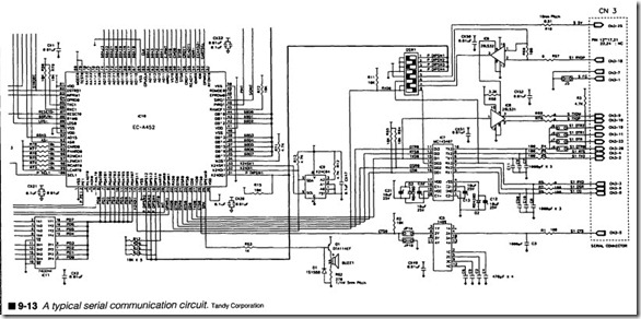
A typical serial communication circuit is shown in figure 9-13. While the array of lines and interconnections might appear daunt ing, the circuit’s operation is remarkably straightforward. Data en ters the printer through the Rx line (pin CN3-18) where it is translated from a bipolar signal into a TTL signal by the line re ceiver IC6. From IC6, data is passed directly to the gate array (IClO), which contains all of the UART and data handling func tions needed by the printer. Similarly, data to be passed back to the printer is converted to serial form by the gate array, then fed to the line driver (IC8), which converts TTL signals into bipolar signals for transmission. Bipolar serial data leaves the printer through Tx line (pin CN3-9). Communication parameters can be set through DIP switch DSWl. DTR and CTS handshaking signals are processed through IC7 and IC5. The proliferation of resistors and capacitors in the circuit serve largely as signal conditioning and filter components.
Isolating the communication circuits
A communication interface involves much more than printer cir cuits. The successful transfer of data requires proper operation of a computer and interconnecting cable as well. Trouble in any one of these three areas can interrupt the flow of data. Before you dis assemble your printer, you should isolate the problem to the printer itself. The quickest and most certain way to do this is to test a known-good printer on your existing computer using the same parallel or serial interface. If a new printer works properly, then you have ruled out the computer, cable, or software program. If a known-good printer also fails to operate, you might have a problem in your computer, its software configuration, or the cable.
Once you have isolated the problem to your printer, run a printer self-test or use the PRINTERS utility. This will test a printer’s motors, carriage, print head, power supply, and most of its logic and driving circuitry. Ifthe test pattern looks good, you can be pretty certain that the printer’s interface circuit is defective. If the test pattern is faulty, then your printer is suffering from a defect elsewhere.
Troubleshooting communication circuits
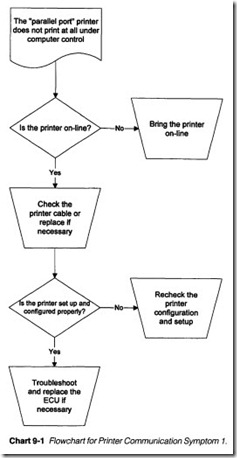
Symptom 1 The printer’s self-test looks correct, but the “parallel port” printer does not print at all under computer control. Refer to Chart 9-1. A “printer not ready” error might occur at the com puter. Check the printer’s on-line status; if the printer is off-line, it
will not receive data sent from the computer. Virtually all printers have an LED on the control panel, which is illuminated when the printer is on-line. If the printer is off-line (the “on-line” LED is dark), try pressing the on-line button or reinitialize the printer. If the printer refuses to go on-line, check the paper supply.
Examine your interface cable. If it is loose at either end, data and handshaking signals might not reach the printer. If you have run another printer successfully using your current cable, then the ca ble is almost certainly good. If you are in doubt, disconnect the ca ble, and use your multimeter to measure continuity across each conductor (or just try another known-good cable). Wiggle theca ble to stimulate any possible intermittent connections. Replace any defective interface cable.
Next, check the printer setup parameters in the PC’s printing appli cation, especially under the Wmdows or Wmdows 95 “printer” dia log(s). Make sure that the correct printer driver is loaded, and see that your printer is selected as the “default” printer. Also check that the correct “printer port” is selected. For example, if Windows is at tempting to print to a Panasonic DMI printer on LPT2, but you have an HP DeskJet printer on LPT1, the printer simply will not work. Check any unique DIP switch settings in the printer to be certain that they are appropriate. If another parallel printer works, check its DIP switch settings against those of the defective printer.
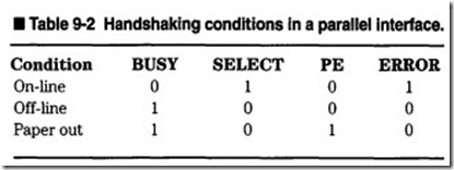
If everything is configured properly up to this point, disassemble your printer and expose its communication circuitry. Refer to the parallel circuit of figure 9-8. With the printer connected and run ning, use your logic probe or oscilloscope to examine each hand shaking line. There are four key status signals that communicate the current operating conditions of your printer: Busy (pin 11), Select (pin 13), Paper Out (pin 12), and Error (pin 32). Table 9-2 illustrates the interaction of these status lines versus the printer’s “on-line” or “off-line” condition. If you fmd these four signals at their appropriate levels when the printer is on-line, the printer should be ready to accept data. If on-line conditions are incorrect, a problem exists in your interface or main logic circuitry. Check the supporting logic that provides your handshaking signals. Infig ure 9-8, the 74LS07 buffer IC provides signal conditioning for many handshaking signals. If the inputs to any of those gates are different than the outputs, the buffer IC might be faulty. If hand shaking signals are correct back to the gate array IC (not shown in figure 9-8), replace the ASIC or gate array that directs handshak ing signals.
If your examination proves inconclusive, or if you do not have the time or inclination to perform this type of component-level exam ination, replace the main logic portion of your ECU. For impact and ink jet printers, this is typically a single board. For EP print ers, you should replace the main controller board or communica tions submodule.
Symptom 2 The printer’s self-test looks correct, but the “serial port” printer does not print at all under computer control. A “printer not ready” error might occur at the computer. Check the printer’s on-line status; if the printer is off-line, it will not receive data sent from the computer. Virtually all printers have an LED on the control panel that is illwninated when the printer is on-line. If the printer is off-line (the “on-line” LED is dark), try pressing the on-line button or reinitialize the printer. If the printer refuses to go on-line, check the paper supply.
Examine your interface cable. If it is loose at either end, data and handshaking signals might not reach the printer. If you have run another printer successfully using your current cable, then the ca ble is ahnost certainly good. If you are in doubt, disconnect the ca ble, and use your multimeter to measure continuity across each conductor (or just try another known-good cable). Be careful. Many serial cables flip (or reverse) the Tx and Rx lines between computer and printer, so you must take that into account when making measurements. Wiggle the cable to stimulate any possible intermittent connections. Replace any defective interface cable.
Next, check the printer setup parameters in the PC’s printing ap plication, especially under the Windows or Windows 95 “printer” dialog(s). Make sure that the correct printer driver is loaded, and see that your printer is selected as the “default” printer. Also check that the correct “printer port” is selected. For example, if Windows is attempting to print to a Panasonic DMI printer on COM2, but you have an HP DeskJet printer on COMl, the printer simply will not work.
Serial conununication requires a fairly large number of parameters to specify the structure and speed of each serial character. Word length, stop bit(s), parity, baud rate, and handshaking method are some of the more conunon options that can be selected when set ting up a serial conununication link. However, each option must be set exactly the same way at both the computer and printer. If not, a printer cannot interpret just where data starts and ends. The re sulting confusion will cause an erratic jumble of unintelligible print (if it prints at all). Communication parameters are usually set by a series of jumpers or DIP switches within the printer. Check these settings against those listed in your user’s manual. If you have run another printer, check its configuration and compare settings.
If problems persist, there is probably a fault in the serial commu nication circuit. Refer to the circuit fragment of figure 9-13 for typical troubleshooting. There are only a handful of components involved in serial conununication: a line receiver, line driver, gate array, and several handshaking gates. If the printer appears on line, use your oscilloscope and check the DTR (Data Terminal Ready) line. If the printer is ready to receive data, DTR should be at a positive voltage (+5 to + 15V depending on the serial interface design). If the DTR line is at a negative voltage, the computer will not send data because the printer is not ready. If DTR is locked low, check the line transceiver circuit (i.e., IC7). If the DTRO (IC7 pin 11) is high but DTRO at the output (IC7 pin 10) is low, IC7 is probably defective and should be replaced. If DTRO (IC7 pin 11) is locked low, suspect a fault in the gate array (IC10).
If DTR (CN3-20) is high as expected and conununication still fails to take place, suspect a problem in your line transceivers. Use your oscilloscope to check the receive (Rx) signal (CN3-3) and follow that signal to the line receiver (IC7 pin 9). Check the line output (IC7 pin 12). If received data is present at the input, but missing at the output, the line receiver (IC7) is defective and should be re placed. If data is present at the line receiver output, the DIP switches at DSW1 might be set improperly, or there is a problem in the gate array (IC10) that should be replaced. You can also check the transmit (Tx) signal (CN3-2) and follow that signal to the line driver (IC7 pin 5). If the Tx signal is missing, check the line driver input (IC7 pin 15). If the outgoing data to the line driver is present, the line driver (IC7) is probably defective and should be replaced. If the outgoing data is missing, there is probably a fault in the gate array (IC10) that should be replaced.
If your examination proves inconclusive, or if you do not have the time or inclination to perform this type of component-level exam ination, replace the main logic portion of your ECU. For impact and ink jet printers, this is typically a single board. For EP print ers, you should replace the main controller board or communica tions submodule.
Memory
A printer accepts data and control codes from its host computer, processes and interprets that information, then operates its print head and transport mechanisms to transcribe that information into a permanent form. Solid-state memory plays an important role in this operation. Figure 9-2 illustrates a typical arrangement of memory (marked RAM/ROM memory) within an ECU.A printer operates on a fixed set of instructions, its own internal program that tells main logic how to communicate, how to operate its print head and transports, what function each dip switch repre sents, how to interpret control panel operations, and so on. This program resides permanently inside the printer, so it is stored in a permanent memory device. Other data, such as font styles and en hancements, can also be stored in permanent memory. On the other hand, some information changes constantly; characters and control codes received from the computer are only stored until they are processed. Main logic also requires locations to store control panel variables and results from calculations. Temporary memory devices are used to hold rapidly changing information during printer operation.
Memories are arranged as a matrix of storage cells, each specified by their own unique location (or address). The number of avail able addresses in a memory device depends on the number of ad dress lines available. For example, a memory IC with eight address lines can access 28 or 256locations. Ifyour IC has 12 address lines, it can access 212 or 4,096 locations. Each address can hold one, two, four, eight, or more bits, depending on the organization of the particular device. A one megabit (Mbit) memory could be arranged to hold one bit in 1,048,576 (1M) individual locations, four bits in 262,144 (256K) locations, eight bits in 131,072 (128K) locations, or some other arrangement. While PCs typically use large, low-bit memory devices (e.g., 1M x 1bit), conventional printers frequently use “wider” devices (e.g., 32K x 8 bit).
Permanent memory
As the name suggests, information in permanent memory is re tained at all times, even while power is removed from its circuit. You might hear permanent memory referred to as nonvolatile or read only memory. There are three basic classes of nonvolatile memory that you should be familiar with: ROM, PROM, and EPROM. Your printer might employ any of these memory types, although the sim pler ROM type devices are encountered most frequently.
ROM
A ROM (Read-Only Memory) is the oldest and most straightfor ward class of permanent memory. Its information is specified by the purchaser, but the actual IC must be fabricated already pro grammed by the IC’s manufacturer. ROMs are rugged devices. Be cause their program is actually a physical part of the device, it can withstand a lot of electrical and physical abuse, yet still maintain its contents. However, once a ROM is programmed, its contents can never be altered. If a program change is needed, an entirely new device must be manufactured with any desired changes, then installed in the circuit.
PROM
The PROM (Programmable Read-Only Memory) can be pro grammed by a printer manufacturer instead of relying on a ROM manufacturer to supply the programmed devices. A PROM can be programmed (or burned) once, but it can never be altered. Fac tory-fresh PROMs are built as a matrix of fusible links. An intact link produces a binary 0, while a burned link produces a binary 1. One link is available for each bit in the device. A special piece of equipment called a PROM Programmer is fed the desired data for each PROM address. It then steps through each PROM address and burns out any links where a binary 1is desired. When the PROM is fully programmed, it contains the desired data or program.
EPROM
An EPROM (Erasable PROM) can be erased and reprogrammed many times. Binary information is stored as electrical charges placed across MOS (Metal Oxide Semiconductor) transistors. One transistor is provided for each bit in the device. An absence of charge is a binary 0, while the presence of charge is a binary 1. Programming is very similar to that of a PROM. An EPROM pro grammer is loaded with the desired information for each location. It then steps through each location and locks charges into the appropriate bit locations. To erase an EPROM, you must remove charges from every bit location. That is accomplished by exposing the memory device (the die itself) to a source of short-wavelength ultraviolet light for a prescribed period of time. Light is introduced through the transparent quartz window on top of the IC package.
An example of permanent memory
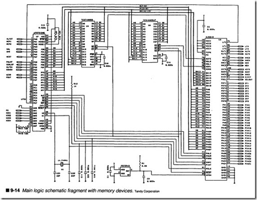
The memory layout for a Tandy DMP203 dot-matrix printer is il lustrated in figure 9-14. IC U4 is the permanent memory (a PROM). The 17 address lines support 131,072 (128K) locations, and the eight data lines indicate eight bits per address. In total, the ROM is classified as a 128KB ROM. Of course, address and data lines alone are not enough to run the IC. Control lines must also be added. The ROM uses two control signals: a ‘Chip Enable (‘CE) signal, and an ‘Output Enable (‘OE) signal. When the ROM is needed to supply instructions and data, the ‘Chip Select signal is driven low by the managing gate array (U3). Then data at the se lected address will be available. Finally, the ‘Output Enable signal is driven low by the microprocessor (U7) to put data on the data bus (D0 to D7).
Temporary memory
Digital information contained in temporary memory can be altered or updated frequently, but it will only be retained as long as power is applied to the device. If power fails, all memory contents will be lost. This kind of memory device is referred to as volatile, read write, or Random Access Memory (RAM). The term random ac cess refers to the fact that the device can be accessed for reading or writing operations as needed. The two basic types of RAM that you should know are static and dynamic.
SRAM
A static RAM (SRAM) uses conventional logic flip-flops (called cells) to store information. One cell is provided for each bit. A read/write control line is added to select between a read or write op eration. During a write operation, any data bits existing on the data bus are loaded into the cells at the address specified on the address bus. If a read operation is selected, data contained at the selected address is made available to the data bus. Once data is loaded into a static RAM, it will remain until it is changed, or until power is re moved. SRAMs are used heavily in printers.
DRAM
Dynamic RAM (DRAM) devices use small MOS cells to store data in the form of electrical charges. While reading and writing opera tions remain virtually identical to those of SRAMs, DRAMs must be “refreshed” every few milliseconds, or data will be lost. Refresh is provided by a combination of external circuitry and circuits within the DRAM chip itself. Although the need for refresh increases the complexity of a memory circuit, MOS technology offers very low power conswnption and a large amount of storage space as com pared to most SRAM devices. DRAM is used primarily in PCs, but you might encounter DRAM in EP printers that demand substan tial amounts of memory.
An example of temporary memory
You can see an example of temporary memory in figure 9-14. IC U6 is an SRAM. With 15 address lines, the RAM can access 32,768 (32K) addresses. Eight data lines provide eight data bits to each address, so the SRAM is 32Kx8 (32KB) device. Like the ROM, an SRAM uses a ‘Chip Enable and ‘Output Enable signal to manage the flow of data. In addition, the SRAM needs to differentiate be tween reading and writing, so a ‘Write Enable (‘WE) line is in cluded. When the signal is low, data on the data bus will be written to the selected address. When the signal is high, data at the se lected address will be placed on the data bus.
Troubleshooting memory
Memory is usually one of the most reliable sections of an ECU, but when a failure does occur, the results can manifest themselves as lost characters, occasional operating hang-ups for no apparent reason, or up-front initialization failure. The difficulty in testing memory is that it is virtually impossible to tell for sure just what lo cation or bit the problem is corning from. In order to properly test a RAM device, a known pattern of data would have to be written to each location, then read back and compared to what was written. If there is a match, that location is assumed to be good. If there is no match, that location (and the entire IC) is defective. Most printers perform a memory check on initialization. Unfortunately, there is no way of performing this sort of test in the printer during operation.
ROM devices are even more difficult to test. Each location would have to be read and compared against a listing of data at each ad dress. If there is a match, the location is valid. If there is no match, the location (and the entire ROM) is defective. Even if you could check each ROM address, you have no listing of its program for comparison. The bottom line here is that unless your printer specifically checks memory on initialization and reports such er rors through error messages, LED flashes, or beep patterns, it is extremely difficult to test memory directly. Still, there are some memory symptoms that you should be familiar with.
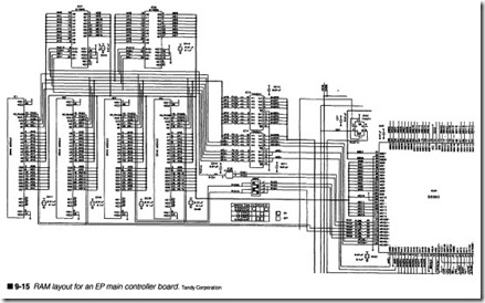
Symptom 1 A RAM error is indicated with a text message or blink ing LED. While an error message might be relatively easy to un derstand, blinking LEDs can be a bit more difficult to follow. Typically, the Power LED will blink on and off three times quickly, go dark for about 500 ms, then repeat. Of course, your own printer might use a different error sequence. For relatively simple print ers, such as the DMP 203 shown in figure 9-14, a RAM error indi cates that the SRAM (U6) has failed. However, the microprocessor also frequently uses a small amount of internal RAM, so if the problem persists after replacing the SRAM, try replacing the mi croprocessor. If problems still continue, or you prefer to avoid component-level work, replace the ECU board entirely.The problem is a little more complicated with EP printers, as you can see in the schematic fragment of figure 9-15. The Tandy LP800 uses a series of 8-bit DRAM modules. However, if you study the memory layout closely, you will note that the DRAM modules are paired, allowing a 16-bit memory data bus to the main pro cessing gate array (IC25). This design is further complicated by the addition of refresh controllers (IC36 and IC37) constantly working to keep the printer’s data intact. The refresh signals can typically be identified by RAS and CAS prefixes. You can insert a mix of 0.5MB and 1MB DRAM modules, but you must set the DIP switches in DSW2 in the proper configuration to recognize the cor responding modules. When a memory fault occurs here, there is a lot more ground for you to cover.
If the DRAM modules are hard-soldered to the main controller board, your best course is often just to replace the main controller entirely; otherwise, you would systematically have to replace each DRAM unit until the defective one was discovered. When the DRAM units are available in replaceable modules, it is possible to try a new module in each location systematically until the defect disappears. If DRAM problems persist, suspect a fault in the re fresh controllers (IC36 and IC37) or the managing gate array (IC25). If the problem persists, replace the main controller board.
Symptom 2 A ROM checksum (or similar) error is reported. Per manent memory holds the instructions that run a printer, as well
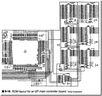
as any resident fonts. When the printer is first initialized, a check sum value for each ROM is calculated, then compared to the checksum stored in each ROM. If the calculated value matches the stored value, the ROM is considered good; otherwise, the ROM is assumed bad, and an error message is generated. For relatively simple printers, the firmware and font data can be stored on a sin gle IC (such as U4 in figure 9-14). For more complex printers, however, a number of permanent memory devices are needed, as shown in figure 9-16. The EP printer’s fmnware is stored on two ROMs (IC26 and IC28). Note that these ROMs are not indepen dent; one is the odd ROM (data bits 0 through 7), while the op posing ROM is even (data bits 8 through 15). This supplies a 16-bit data path. There are also two sets of font ROMs: outline font ROMs (IC31 and IC30) and filled font ROMs (IC27 and IC29).
Typically, ROMs are DIP-type ICs inserted into sockets on the motherboard. This means that ROMs are often easy to replace, if you can find them. Replacement ROMs are not always easy to come by. The first ROMs to suspect are the firmware ROMs be cause they hold the instructions for your printer. A firmware fail ure will allow the printer to malfunction during operation. Font ROM problems are generally less catastrophic. At worst, certain font styles and sizes might appear distorted. If you cannot locate replacement ROMs (or new ROMs have no effect), replace the ECU or main controller board.
Control panel
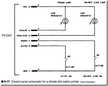
The control panel serves several purposes. It allows you to operate certain immediate functions, such as form feed, line feed, reset, or on/off line. Certain key combinations let you alter options and run ning modes. In some printers, for example, pressing the reset and form feed keys together allow you to select a different font style or character pitch. As another example, pressing form feed and line feed together might cause the printer to execute a self-test cycle. Your user’s manual will specify the exact key strokes and their ef fect. Finally, indicators are included to display various printer sta tus conditions, such as “on-line” or “paper out.” More advanced control panels offer an LCD that displays full text prompts and in formation. Figure 9-17 illustrates a schematic for a simple control panel. Most control panels connect directly to ASIC or micro processor circuits as figure 9-2 shows.
As you might expect, there is little that can go wrong with the “con trol panel” of figure 9-17. LEDs and sealed switches are hardly sen sitive components. However, switch operation is very important to the printer; marginal switch operation can make operating the printer a frustrating chore. The “control panel” connector (CN7) is attached to the ECU main board. For simple printers, the con trol panel is attached directly to the main microprocessor or mi crocontroller. You can see the control panel signals on the left side of the microprocessor (U7) in figure 9-14.
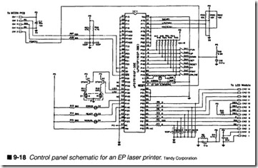
While the control panel of figure 9-17 appears pretty simple, there are much more complicated designs as shown in figure 9-18. EP printers employ microcontrollers that are custom-designed to sup port an LCD module (not shown in figure 9-18). In addition to ami crocontroller (IC1), there are many more S\vitches (SWl to SW8) to deal with, and several more LEDs (Dl to D4). It is interesting tore alize that the switches and LEDs are tied directly to the microcon troller, so IC1 is not only a processing element, but it also includes the circuitry to drive real-world devices. This high level of integra tion reduces the need for multiple ICs. Communication between the
microcontroller and the remainder of the ECU (typically the me chanical controller board inan EP printer) is accomplished through a single serial line (marked PD at CNl pin 3). Thus, when a message or error code must be displayed, the condition is transmitted seri ally to the control panel microcontroller, which interprets the mes sage, drives LEDs, and displays the actual text on the LCD module. Conversely, the microcontroller will transmit messages to the me chanical controller as various switches and switch combinations are pressed. You can see this data with an oscilloscope or logic probe, al though the data stream is hardly meaningful to the casual observer.
Understanding sealed switches
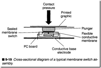
Most printers (conventional and EP alike) use sealed membrane type switches covered by a solid plastic strip containing the graph ics for each key. A cross-sectional diagram of this arrangement is shown in figure 9-19. Membrane switches use a flexible metal di aphragm mounted in close proximity to a conductive base elec trode at the switch bottom. Ordinarily, the diaphragm and base do not touch, so the switch is open. When you touch the proper loca tion on a desired graphic, a solid plunger deforms the metal di aphragm and causes it to contact the base electrode. This closes the switch. After you release the graphic, the metal diaphragm below returns to its original position and opens the switch again. The diaphragm’s design might “snap” a bit when pressed to provide you with a tactile sensation of positive contact.
Unfortunately, membrane switches are subject to breakdown with age, use, and environmental conditions. Although membrane
switches are sealed to prevent disassembly, most are not hermeti cally sealed to keep out moisture and dust. Over time, oxidization can occur that prevents positive contact between the membrane and electrode. Regular use can also wear away at both contact sur faces and eventually cause bad or intermittent contacts; the switch might not always respond when you press it. Finally, regu lar use can cause the diaphragm to stretch or dislodge from its mounting. This can lead to a short circuit if the diaphragm fails to snap open when released. Ultimately, switch problems occur quite frequently in older control panels.
Troubleshooting a control panel
Symptom 1 The control panel does not function at all. No keys or indicators respond. Otherwise, the printer appears to operate nor mally under computer control. Open your printer enclosure and expose the control panel circuit. Make sure that any connector(s) or wiring from the panel are installed properly and securely. If you have just finished reassembling the printer, perhaps you forgot to reconnect the control panel, or reconnected it improperly. Inter connecting wiring might have been crimped or broken during a previous repair.
It is rare that a simple control panel will fail outright (such as the circuit in figure 9-17). When a total failure occurs in this case, the trouble is almost always in the ECU rather than the control panel; the microprocessor or microcontroller that manages the keyboard has probably failed. Try replacing the ECU. However, when prob lems occur with a sophisticated control panel (such as the circuit in figure 9-18), it is more likely that the control panel’s local mi crocontroller has failed. It is the local microcontroller that handles the LEDs, switches, and LCD panel (if included). Try replacing the local microcontroller. If this is not possible, replace the entire control panel module. In most cases, a new control panel should solve your problem, but in the rare event that problems persist, the fault will be in the ECU (specifically the mechanical controller board for EP printers). Your best course then is simply to replace the me chanical controller board.
Symptom 2 One or more keys is intermittent or defective. Exces sive force or multiple attempts might be needed to operate the key(s), but the printer appears to operate normally otherwise. You will find this symptom most often in older, heavily used printers. In almost every instance, this symptom is simply the result of faulty keys. Typical printer keys are built using pressure-sensitive con
tact switches. With age and use, the switch contacts become unre liable, even stubborn.·Ideally, the preferred course would be to re place the questionable switches. Unfortunately, replacement switches are often not available. If you cannot replace the defec tive keys, you will have little choice but to replace the entire con trol panel module.
Symptom 3 One or more LED indicators fail to function. Printer appears to operate normally otherwise. LEDs are notoriously reli able devices (lifetimes of 30,000 hours or more is not uncommon), so it is unlikely that the LED itself has failed. Rather, you should frrst suspect the circuit that manages the LED. Consider the cir cuit of figure 9-18, and examine the LEDs D2, D3, and D4. Notice that they are all powered from a common source (usually +5 V). Start your examination by checking this voltage with your multi meter. If the supply voltage is low, check your de power supply.
Now, when supply voltage is present, each LED will be on when the cathode side of the LED is grounded (performed by circuits in side ICl). Use a multimeter or logic probe and check the cathode side of each diode. If the LED is off, you should see about +4.5 V (or a logic 1) on the LED’s cathode. If the LED is on, you should read about +0.8 V or so. If the cathode voltage is low but the LED is dark, the LED is defective and should be replaced. If the LED should be on but the cathode voltage is still high, the correspond ing control circuit (in this case ICl) might be defective and should be replaced.
If you are unable to troubleshoot LED signals, you can replace the suspected subassembly. For simple control panel systems, prob lems are typically in the ECU, so try replacing the ECU entirely. For EP-type control panels, you can try replacing the control panel module. In the rare event that problems continue, try re placing the mechanical controller board.
Symptom 4 The LCD display is dark or displaying gibberish. This symptom arises inhigh-end printers that employ LCDs in addition to LED indicators. Start by checking the LCD module’s connector to see that it is installed properly and completely. If the control panel is working otherwise, chances are that the LCD module is defective, so try replacing the LCD unit. If the control panel has failed (i.e., switches not responding), the local microcontroller has probably failed. Replace the microcontroller. If you cannot replace the microcontroller, replace the control panel subassembly entirely.
Driver circuits
Printers depend on electromechanical devices (e.g., motors and solenoids) for proper operation. Unfortunately, logic circuits sim ply cannot provide the power needed to drive an electromechani cal device directly. Instead, driver circuits must be inserted between the ECU logic and the particular device to be driven. For example, a driver circuit can convert a 5-V, lO-rnA TTL pulse, into a 24-V, 1.5-A pulse needed to fire a DMI print wire. Conventional printers use three sets of drivers: print head drivers, carriage mo tor drivers, and paper advance motor drivers. Electrophotographic printers often use a single set of motor drivers to operate the drum, along with drivers to actuate pickup and registration roller clutches. Before you review some actual driver circuits, you should understand the operation of transistor switches.
Transistor switches
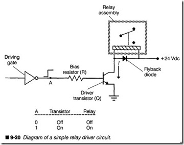
Transistors can be used as linear amplifiers or solid-state switches. When configured as a linear amplifier, a transistor’s output signal would appear as a larger duplicate of its input signal. Digital sig nals, however, are only on or off, so there is no real advantage to providing linear ampliflcation. Instead, transistor circuits are con figured as “switches” that operate either totally on or totally off depending on the condition of its input signal. Consider the main logic circuit in your printer. It executes preprograrnmed steps based on input from the computer, control panel, and any sensors available in the circuit. Suppose at some point in its program, main logic needs to activate a pick-up roller clutch or operate a motor. TTL devices alone can only source or sink a few milliamps of cur rent, hardly enough power to drive these real-world devices. A “driver” is added that will accept logic signals, and amplify them enough to power such things as a motor or relay. The transistor is ideal for this function because it needs very little base current, and it can carry relatively large currents in its collector. Figure 9-20 is just one typical example of this type of interface.
\\’hen the driving gate’s output is off Oogic 0) at point “A,” no cur rent flows into the transistor’s base, so it is turned off (or cutoff), and it acts like an open switch (no collector current flows and the relay remains off). If the driving gate turns on Oogic 1) at point “A,” its TTL output supplies enough current into the transistor’s base to fully activate (or saturate) the device. The transistor then acts like a closed switch (current flows, which turns on the relay). This is the same technique used to operate many electromechanical devices in your printer. Although discrete transistors are often used as drivers, some printers use integrated drivers-driver transistors fabricated onto IC structures.
Print head drivers
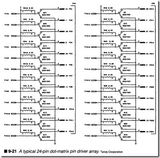
Moving-carriage print heads form images by firing discrete points as the head passes across the page surface. Each “discrete point” must be fired independently by the ECU, and driver circuits are re quired to interface the logic to the print wires, ink nozzles, or what ever mechanism the particular print head is using. Figure 9-21 shows you the driver schematic for a 24-pin DMI print head. As you see, the driver circuit is really quite straightforward; a separate transistor switch is used for each print wire. Each of the “PIN” sig nals (PINl through PIN24) is generated by a gate array in the ECU’s main logic (the IC marked U3 in figure 9-14). When a PIN signal becomes logic 1, the corresponding transistor saturates, causing current to flow in the print wire solenoid. This action fires the print wire. Note that the output connector (marked CN6) is where the print head cable attaches to the ECU.
When a print wire driver fails, it can fail in an open or shorted con dition. The open failure is most common, and prevents the corre
sponding print wire from firing. The result is a horizontal white line in the print. On the rare occasions when a print wire driver fails in the shorted condition, the print wire remains extended.
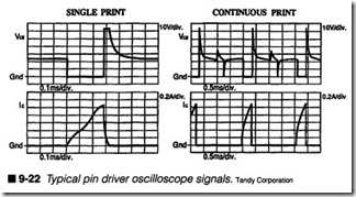
This often appears as a horizontal black line in the print, but it might also tear the ribbon. You can test a driver transistor with any oscilloscope. Set your oscilloscope to measure TTL logic levels, and check the base (B) of the suspect transistor. If the TTL signal is missing, the gate array IC in the printer’s main logic is probably defective and should be replaced. If the TTL logic signal is pres ent, set your oscilloscope to measure 20-30-V signals, and check the collector (C) of the transistor. You should see a driver signal, such as the one in figure 9-22. If this signal is absent, the transis tor has probably failed and should be replaced. If this signal is pres ent (but the print wire is not working), the print head cable is defective, or the print wire is jammed or broken, so try cleaning or replacing the print head assembly.
Carriage motor drivers
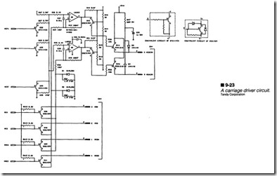
The carriage transport system is responsible for carrying the print head back and forth across the page. At the heart of this system is the carriage return (CR) motor, which is typically a four-phase stepping motor. The circuit in figure 9-23 is used to drive a CR mo tor. There are two major portions to this circuit: the phase drivers and the voltage drivers. You will probably recognize the four-phase driver transistors (Q38 to Q41) immediately. These transistors provide the high-energy pulses that actually step the CR motor.
While this might be all that is needed for a CR driver, there are some additional factors to consider; most important is that the carriage must be stepped at different rates depending on what state the printer is in. As a result, the CR motor must be set to dif ferent supply voltages. The upper portion of figure 9-23 is used to
set the operating voltage (and thus the stepping speed) of the car riage. The step signals (HCA, HCB, XHCA, and XHCB) are pro duced by the managing gate array (U3 in figure 9-14), while the step rate signals (HCP1, HCP2, and HCST) are generated by the microprocessor (U7 in figure 9-14). All of the output signals (marked CN4) are connected directly to the CR motor assembly.
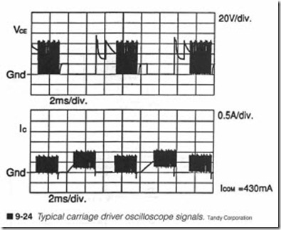
Carriage problems can typically be traced to either a fault in the phase drivers, or a problem in the step rate control circuit. The phase drivers are straightforward to troubleshoot (the same ap proach used for the pin drivers of figure 9-21), and you should find collector signals similar to those shown in figure 9-24. When trou ble strikes the step rate circuit, you will often fmd the trouble in high-energy components, such as D3 or D4, or Q42 through Q45.
Line feed motor drivers
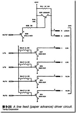
The paper transport system is responsible for carrying each page through the printer. Regardless of whether the transport is a tractor-feed or friction-feed mechanism , both are driven by a single line feed (LF) motor. The LF motor itself is typically a four-phase stepping motor, and the LF driver circuit is shown in figure 9-25. Notice the similarities between this circuit and the CR motor cir cuit of figure 9-23. Basically, the LF driver circuit is composed of four-phase driver transistors that actually provide the high-energy pulses that run the LF motor. There is also a voltage cutoff circuit (composed of Q30, Q35, and their related components) that is used to supply power to the LF motor windings. The phase control signals (LFA, LFB, XLFA, and XLFB) are produ ced by the manag ing gate anay (U3 in figure 9-14), while the power enable signal (XLFST) is supplied directly from the microprocessor (U7 in fig ure 9-14). All of the output signals (marked CN5) are connected directly to the LF motor.
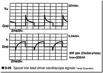
Line feed problems can typically be traced to either a fault in the phase drivers, or a problem in the line feed enable circuit. The phase dtivers are straightforward to troubleshoot (the same ap proach used for the pin drivers of figure 9-21), and you should find collector signals similar to those shown infigure 9-26. When trouble strikes the line feed enable circuit, you will often find the trou ble in high-energy components, such as Q30 or Q35.
EP driver circuits
Electrophotographic printers use much of the same electronic wizardry that moving-carriage printers do. The main motor is the heart of an EP mechanical system, and it provides all of the force needed to pick up a page and carry it through the printer. Nor mally, the main motor runs throughout the printing cycle, but pick-up and registration units only need to work for brief periods; thus, some means is needed to engage and disengage the pick-up and registration assemblies as needed. To address this problem, solenoids are used as “clutches” to transfer force to the pick-up and registration assemblies as needed. The mechanical controller board provides the drivers needed to operate the main motor and
solenoid clutches. When main motor or clutch operation problems arise, you should suspect a fault in the mechanical controller board.
Troubleshooting a driver circuit
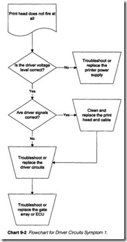
Symptom 1 Print head does not fire at all. Refer to Chart 9-2.
Other printer operations appear correct. The printer also fails to print during a self-test. Review the print head driver circuit illustrated in figure 9-21. There are typically four reasons why the moving carriage print heads fail to operate: the print wires have jammed or internal wiring has failed, the print head cable has failed, the print head drivers have failed, or the managing gate array (ECU logic) has failed. When a complete failure occurs (the print head fails to work at all), chances are that your interruption has oc curred in a common signal wire, such as a ground or voltage line.
To best detennine the nature of this problem, reinitialize the printer and use your multimeter or oscilloscope to measure the driver supply voltage. For a pin driver circuit, such as figure 9-21, you should expect to fmd +24 Von pins 14, 16, 17, 19, 20, and 32 of CN6. If the +24 V is low or missing, you might have a fault in the printer’s power supply. Also check the +5-V supply output to be sure that appropriate voltage is available to the printer’s logic. Ad dress the symptoms of Chapter 8 to troubleshoot the power sup ply in more detail.
If the supply voltage is correct, run the printer (use the PRINT ERS utility to generate a test page) and use your oscilloscope to measure the pin signals at the collector (C) of each driver transis tor. In normal operation, you should fmd pin signals similar to the waveform of figure 9-22. If you find each pin signal as expected (but the print head still does not print), either your print head or print head cable has failed. Check the installation and continuity across your print head cable, and replace the cable if necessary. Then try replacing the print head.
If the pin signals are missing, check the logic signals at the base (B) of each driver transistor. If the base signals are missing, the gate array responsible for generating those signals has failed. Try replacing the gate array, or replace the entire ECU. If the base sig nals are present (but the collector signals are absent), suspect a ground fault. Notice in figure 9-21 how the emitter (E) of each driver transistor is tied to a common ground. Inspect the circuit carefully and note if any circuit interruptions occurred in the ground line; this can disable the entire driver array. If you are un able to locate a printed wiring fault, replace the ECU.
Symptom 2 Print contains one or more white (missing) or black lines. All other printer operations appear correct. Symptoms per sist during a self-test. Always start by powering down the printer and cleaning the print head. It is not unusual for accumulations of ink and paper residue to jam a print wire. If problems persist, use your oscilloscope to measure the driver pulses at the collector (C) of the suspect driver transistor(s) such as in figure 9-21. You should observe pulses similar to those shown in figure 9-22. If the pulses are present (but the print wire does not fire), there might be a fault in the print head cable or the print head wire itself. In spect the print head cable and replace it if necessary. Otherwise, replace the print head assembly.
If the collector signal(s) are absent, use your oscilloscope to mea sure signals at the transistor’s base (B) pin. When the base signal is present (but the collector signal is absent), the driver transistor has failed and should be replaced. Be sure to use an exact re placement part. If you cannot obtain a replacement part, try re placing the ECU. If the base signal is absent, suspect a fault in the gate array, which provides the base signal. Replace the gate array or replace the ECU outright.
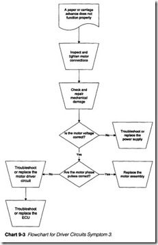
Symptom 3 A paper or carriage advance does not function properly (if at all). Refer to Chart 9-3. Always start your investigation by in specting the motor connections. Turn off and unplug the printer,
then check the cables to your suspect motor. Try reinstalling the motor connector at the ECU. Also check for any obstructions or damage to the LF or CR mechanics. You might need to address mechanical problems as described in Chapter 10. Next, check the motor voltage by inspecting the +24-V output from the power sup ply. If this voltage is low or absent, troubleshoot or replace the power supply as described in Chapter 8. When the printer is run ning, there should be about +24 Vat pins 5 and 6 of the CR or LF motor. If this motor winding voltage is missing, check the voltage control circuit feeding pins 5 and 6, or replace the ECU.
If the motor voltage is present, use your oscilloscope and measure the motor driver pulses. For the CR motor driver circuit of figure 9-23 and the LF motor driver circuit of figure 9-25, you can see that both stepper motors are driven by an array of four driver tran sistors. Check the motor pulse at the collector (C) or each driver. For a CR motor, you should see pulses similar to figure 9-24, while an LF motor pulse should appear close to the illustration of figure 9-26. When the motor winding voltage is correct and all the motor pulses are present (but the motor does not tum), the motor is probably defective and should be replaced. If one or more motor pulses are absent, check the signals at the base (B) of each driver
transistor. When a base signal is present but a collector pulse is not, the corresponding transistor is defective and should be replaced. If the base signal is also missing, suspect the gate array used to operate the motor drivers. Try replacing the gate array, or replace the ECU outright.
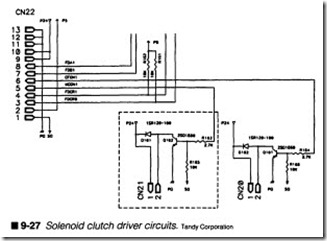
Symptom 4 One or more solenoid clutches have failed. This mani fests itself as either a pick-up or registration problem depending on which solenoid has failed. When dealing with a solenoid, it is ei ther on or off. While the printer is idle, place your multimeter across the solenoid coil; you should read a low voltage. Now run a print cycle. If the voltage across the solenoid jumps up, but no movement takes place, the solenoid is defective or jammed. Check for obstructions that might be jamming the clutch mechanics, or replace the solenoid or solenoid board assembly outright.
If solenoid voltage remains low, however, there is likely a problem in the solenoid driver circuit. With very few exceptions, solenoid driver architectures follow a design similar to the one shown in fJg ure 9-27. Connector CN22 receives logic signals from a gate array on the mechanical controller board. Connectors CM21 and CN20 attach to the physical pick-up and registration solenoids. The driver design for both solenoids is identical. When a logic signal
from the gate array (mechanical controller) becomes logic 1 (i.e., the CFONl signal at CN22 pin 6), transistor QlOl saturates and turns on. This completes the solenoid circuit. When the CFON1 signal returns to logic 0, Q101 turns off, and diode D102 acts as a flyback diode for the solenoid.
Start your investigation by checking for the presence of +24 V. If the solenoid voltage is low or absent, troubleshoot or replace the de power supply as explained in Chapter 8. If the operating voltage is correct, measure the base (B) signal at the switching transistor (i.e., Q101). If the logic signal becomes logic 1 but the solenoid voltage remains unchanged, Q101 is probably defective and should be replaced. Also check D102 and replace it if necessary. If there is no logic signal to operate Q101, the managing gate array on the me chanical controller board is probably defective, but it might be eas ier for you to replace the mechanical controller board.
Main logic
Main logic circuits are the heart and soul of your ECU. It typically includes a main microprocessor, one or more ASICs (gate arrays), at least one clock oscillator, and a variety of interconnecting “glue logic” components needed to tie these parts together. Figure 9-3 illustrates the relative locations of these components. The main logic is responsible for directing all aspects of printer operation.
Microprocessor operations
If a printer could be compared to a symphony orchestra, your main microprocessor would be the conductor. Technically speak ing, a microprocessor is a programmable logic device that can per form mathematical and logical manipulation of data, then produce desired output signals. All microprocessors are guided by a fixed series of instructions (called a program), which is stored in the printer’s permanent memory (the ROM). Although the micro processor found in your printer is often less complex than those found in many computers, you can expect to fmd many of the same signals as shown in figure 9-28. Notice that a set of related signal wires (known as a bus) is often represented as a single wide line. This is done to simplify diagrams and schematics. Arrows are used to depict the possible flow of data. You will find three major buses: the address bus, the data bus, and the control bus.
Address lines
Address lines specify the precise location of instructions or data anywhere in the printer. Address locations might refer to memory locations, operating addresses of registers, ASICs/gate arrays, or other circuit-specific places. Because a microprocessor only generates address signals, it is always the controlling element in a main logic circuit. The Motorola 68000 microprocessor (IC16),
shown in the Tandy LP800 main controller circuit fragment of fig ure 9-28, provides 24 address lines (AO through A23), which can specify 224 or 16,777,216 (16M) unique locations. Simpler print ers (such as the logic circuit of figure 9-14) supply only 16 address lines (AS to A15, data lines DO to D7 are multiplexed to serve as the lower eight address lines), which provides 216 or 65,536 (64K) unique locations.
Data lines
A microprocessor can read data from or write data to any location specified by the address line. Data is sent over the data bus. For example, when the printer is first turned on, its microprocessor will automatically generate an address (usually 0000 hex) and at tempt to read whatever character is available from that address. The microprocessor automatically assumes this to be its first in struction. If memory is defective, or the character at that address is somehow incorrect, the microprocessor will become hopelessly confused. This leads to erratic or unpredictable operation.
During a write operation, the microprocessor will generate an ad dress, then place a valid character on that address. Any device
that is active at that address (such as a RAM IC) will accept this character. Although a microprocessor is capable of writing to any address, not all addresses are able to accept data (such as ROM lo cations). Suppose a paper advance of 25 steps is required at a pa per advance stepping motor. The microprocessor will address its mechanical gate array or ASIC, then place a binary “25” on the data bus. This number would then be translated by the gate array into a series of motor pulses, and delivered to a motor through driver circuits.
Control lines
Finally, a microprocessor is equipped with a number of control lines. A read/write (R/W) signal informs the system whether the microprocessor is performing a read or a write operation at its se lected address. An interrupt request (‘IPLO to ‘IPL2) is sent to the microprocessor whenever the printer must deal with an immedi ate problem or condition. There might be several levels or inter rupts depending on the particular IC in use. Other control lines that you might encounter are the halt (‘HALT) and reset (‘RE SET) signals. There might be many other control lines depending on the age and sophistication of the particular microprocessor. Where address and data signals are often grouped together into bold lines, control signals are typically kept separate (or discrete).
The system clock
A microprocessor is a sequential device; instructions are executed one step at a time. As a result, timing becomes a very critical as pect of the microprocessor’s operation. Timing signals are pro vided by a precision oscillator built into the microprocessor itself. This oscillator is known as the master clock or system clock. To achieve a precise and stable clock, a piezoelectric crystal is added externally (as shown by the crystal X1 in Fig 9-14), and the oscil lator will run at some fraction of the crystal’s resonant frequency. Crystal resonant frequencies are marked right on the part. You will be able to read these clock pulses with your oscilloscope. How ever, not all microprocessors use local crystals. The 68000 CPU in figure 9-28 receives timing pulses at the clock (CLK) line. Clock pulses are generated by a nearby crystal-controlled IC.
The role of ASICs or gate arrays
A single microprocessor or microcontroller cannot possibly handle the wide variety of operations required of a typical printer. The complex logical processing and operations needed to support modem printers demands the equivalent of hundreds of discrete ICs, diodes, and transistors. Unfortunately, the heat and power de mands of so many components would make printers unwieldy. The solution to this problem is to integrate functions onto specialized, VLSI components, known as application-specific ICs (ASICs) or gate arrays. For our purposes, the terms ASIC, gate array, and microcontroller are all used interchangeably. You can see a clas sic example of the gate array in figure 9-29. IC1 is a 100-pin device that performs the bulk of functions needed by an EP mechanical controller board. Of course, there are some other ICs on the board, but IC 1 is the single major processing component. Note the three piezoelectric crystals (Xl, X2, and X3), locking in the IC’s various timing signals. Ultimately, most of the logic signals being generated to manage the mechanical system are originating in a gate array.
Troubleshooting main logic
Most printer troubles do not involve a catastrophic failure of the main microprocessor or a gate array. When a main logic compo nent does become defective, it can effectively disable a mechani cal system, or shut down the printer entirely. This section will present symptoms that represent severe or complete defects in main logic. When you first tum a printer on, main logic performs an initialization procedure that checks the ROM, checks and clears all RAM locations, brings the print head to its “home” position, and
establishes a communication link with the host computer. This procedure can be accomplished in just a few seconds with many conventional printers. An EP printer takes a bit longer because its photosensitive drum must establish a uniform conditioning charge, and the fusing roller must reach a stable operating temperature before printing can take place.
Symptom 1 The printer does not initialize from a “cold start” turn on. Refer to Chart 9-4. There is no visible activity in the printer af ter power is turned on, but power indicators are lit. Self-test does not work. If a printer encounters an error condition during its ini tialization, there will be some visible or audible indication of the fault. Audible tones, flashing light sequences, or an alphanumeric
error code are just some typical failure indicators. Your user’s man ual will list any error codes and their meanings.
If the error is “expected” (that is, an error that is checked and han dled by the printer’s software), the printer will simply wait until the error is corrected. Paper out errors are a commonly “ex pected” error. However, “unexpected” errors can cause the printer to freeze or behave erratically for no apparent reason. ROM or mi croprocessor defects are considered unexpected failures; main logic has no way of dealing with such problems, so there is no way of knowing just how your printer will respond (if it works at all).
Suspect your power supply first. Use your multimeter to measure the logic supply voltage levels in your printer (usually +5 Vde). If this voltage is low or absent, logic devices will not function prop erly (if at all). A low or missing voltage output suggests a defective power supply. Troubleshoot or replace the supply using the proce dures of Chapter 8.
The next area to check is your system clock. Use your logic probe or oscilloscope to measure the oscillator signals on both sides of the piezoelectric crystal (make sure that your oscilloscope or logic probe can measure frequencies as high as the crystal’s rating). If you are using an oscilloscope, there should be a roughly square wave at the frequency marked on the crystal. If the clock signal is low or missing, replace the crystal and stabilization capacitors. If this does not restore your clock source, replace the main micro processor and retest the printer. If you do replace the micro processor, be sure to install an appropriate IC socket frrst if possible. For ECU designs that generate the clock signal from a separate clock/timer IC, try replacing the clock IC. Otherwise, re place the ECU outright.
An initialization process can stall if the microprocessor detects a faulty RAM location. Unfortunately, there is no way to check a RAM IC completely without using specialized test equipment. Some printers might display an error code indicating a RAM error. Re place the RAM chip(s) and retest the printer. If normal operation returns, you have isolated the defective component(s). Be sure to install appropriate IC holders if possible when replacing RAM chips. Printer initialization can freeze if the printer’s program ROM is defective. A bad data or instruction address can easily send the microprocessor into confusion. ROM chips are usually extremely reliable, so their failures are rare. You will have to obtain program ROMs from the manufacturer, or through a reputable distributor.
If symptoms continue, try replacing the main gate array. A failure here can prevent motor operation, disable sensor signals, and cut off communication. The main microprocessor must interact closely with gate arrays, so any fault can “hang up” the main microproces sor’s operation. Of course, you can also just replace the ECU or main controller board outright.
Symptom 2 Printer operation freezes or becomes highly erratic during operation. Typically, you must activate the printer from a “cold start” to restore operation. The self-test might work until the printer freezes. Check the logic supply voltage with your multime ter. You should find about +5 Vdc. If this voltage is low or inter mittently low, logic devices will behave erratically. Troubleshoot the power supply using the procedures of Chapter 8.A microprocessor requires constant access to its program ROM in order to operate properly. Each instruction and data location must be correct, or the main microprocessor will pecome hopelessly misdirected. Ifyou find that the printer only operates to some con sistent point where it freezes or acts strangely, the ROM might be defective. Replace the firmware ROM and retest the printer thor oughly. If normal operation returns, you have probably isolated the problem. Install an appropriate IC socket if possible before insert ing a new ROM 10.
Inspect all of your main logic lOs for any devices that might appear excessively hot, especially if the printer has only been on for a short time. Never touch potentially hot components in a live cir cuit. Instead, smell around the circuit for unusually heated air, or hold the palm of your hand over the circuit. If a part seems unusu ally hot, spray it with liquid refrigerant. If normal operation re turns temporarily (you might have to reactivate the printer or press a reset or on-line button), replace the thermally intermittent component. If your search proves inconclusive, or problems per sist, replace the ECU outright.
Sensors
To operate properly, a printer requires information from the “real world.” For example, the printer must know if there is enough pa per, toner, or ink. The printer also must be able to track head po sition, fusing temperature, or the page’s progress through the printer. A sensor produces an electrical signal based on real phys ical conditions; main logic interprets these signals and makes real time decisions on how to proceed. As you gain more experience
with computer printers, you will learn that there are a wide variety of “sensors” in use. For the purposes of this book, however, there are three types of sensors: resistive, mechanical, and optical.
Resistive sensors
Temperature plays a key role in printer operations. Impact and ther mal printers generate heat as part of their printing process. Thermal printers generate heat intentionally while impact printers produce heat as an unwanted side-effect, but both require head tempera ture to be carefully monitored. As discussed in Chapter 4, EP print ers use a fusion roller assembly. The assembly applies heat and pressure to fix a toner image on paper. Fusion temperature must be carefully maintained to achieve an optimum melt. In each of these cases, a thermistor is used to sense temperature. Thermistors (or thermal resistors) are resistors whose values change in proportion to their temperature. Depending on their formulation, thermistors can be constructed to increase or decrease with temperature.A typical fusing sensor circuit is shown in figure 9-30. The two wire thermistor (not shown) is connected through a cable to the EP mechanical controller board at CN11. Pin TH-1 provides power to the thermistor, and the other end of the sensor attaches to pin TH-2. The resistance of the thermistor, along with R61 and R65 forms a stable network whose voltage output (filtered by C53) is measured by the gate array IC1. It is IC1 that interprets the volt age signal and regulates power to the fusing heater. Iftemperature falls, IC1 detects the change in temperature, and increases the power duty cycle to the fusing heater. Conversely, if temperature climbs, IC1 detects the temperature change and decreases the power duty cycle to the fusing heater.
Mechanical sensors
When position or presence must be detected, a mechanical switch can be used, as shown in figure 9-31. A set of mechanical contacts might be normally open or closed, then actuated by the presence of paper, the print head carriage, closed housings, and so on. Fig ure 9-31 illustrates a simple carriage “home” sensor made with a normally open switch. While the carriage is in motion, the switch is open, so its output equals the value of+V. As the carriage reaches its home position, it closes the switch, which grounds the sensor signal. An ASIC or microprocessor detects this condition andre sponds accordingly.
Optical sensors
Mechanical sensors are simple and inexpensive devices, but they lack reliability over long-term use. Electrical contacts wear out through use and environmental corrosion. They are also subject to electrical ring, an output that might vary on and off for several milliseconds before reaching a stable condition. Optical sensors are irmnune to these problems. A basic optical sensor (called an optoisolator) is shown in the paper-empty sensor of figure 9-32. It is made up of two parts: a transmitter and a receiver. Both are sep arated by a physical gap. The transmitter is usually an infrared (IR) LED kept on at all times. The receiver is typically a photo sensitive transistor that is most sensitive to light wavelengths gen erated by the LED. When paper is present, light generated from the LED is reflected off the page to the phototransistor. The pho totransistor is then saturated, and the PS signal at U7 is logic 1. When paper is missing, LED light is not reflected to the photo transistor, which remains off, so the PS signal becomes logic 0 and an error is generated.
An optical encoder is a slightly more sophisticated application of optoisolators, as shown in figure 9-33. Although many DMI print ers forgo optical encoders, more demanding printers (e.g., ink jet printers) often use an optical encoder to track head position. When a carriage advance motor moves, an optical encoder returns pulses to main logic. These pulses help the main logic determine if the motor has stepped as far as it was told. An incremental en coder uses two individual optoisolators separated by a code disk, which is tied mechanically to the carriage motor. The code disk it self is little more than a clear piece of plastic with opaque mark ings spaced evenly around it. Both optoisolators are aligned so that they cannot be turned on simultaneously. Less expensive en coders might use only one optoisolator. It will still report the same number of pulses, but it cannot determine direction.
As the carriage moves, it turns the code disk. The opaque lines turn each sensor on and off. Each on/off transition corresponds to a step . of the carriage motor, so if the carriage motor turns 500 steps, a train of 500 pulses should be sent back to main logic where they are interpreted by the slave microprocessor or ASIC. If there are too
few or too many pulses, the printer knows that its caniage is not in the desired position. Additional pulses can then be sent, if neces sary, to correct the carriage position. Encoders using two offset op toisolators can be used to determine the carriage’s direction as well as its length of travel. Because both sensors are offset, there is a slight time lag between them. Main logic can identify which pulse leads or lags. For example, if the carriage moves left, the pulses from signal l will lead the pulses from signal2, and vke versa.
Troubleshooting sensors
Before performing sensor checks, be sure to examine any connec tors or interconnecting wiring that ties the sensor into its condition ing circuit. If the sensor checks properly and its conditioning circuit appears functional, there might be a problem with the ASIC or slave microprocessor that interprets and processes sensor signals.
Symptom 1 Paper out alarm shows up on the control panel even though paper is available, or it does not trigger when paper is ex hausted. Refer to Chart 9-5. If your paper sensor is a mechanical switch, place your multimeter across its leads and try actuating it by hand. You should see the voltage reading shift between a logic 1 and logic 0 as you trigger the switch. If you meas ure some volt age across the switch but it does not respond (or responds only in termittently) when actuated , replace the defective switch. If it responds as expected, check its contact with paper to be sure that it is actuated when paper is present. You might have to adjust the switch position or thread paper through again to achieve better contact.
Check an optical paper sensor by placing your multimeter across the photosensitive output and try to actuate the sensor by hand. This might involve placing a piece of paper or cardboard in the gap between transmitter and receiver. You should see the phototransis tor output shift between logic 1 and logic 0 as you trigger the op toisolator. If it does not respond, check for the presence of dust or debris that might block the light path. If excitation voltage is pres ent, but the phototransistor does not respond, it is probably defec tive. Replace the optoisolator. Measure voltage across the LED transmitter. You should find a typical voltage drop of 1.3to 3.6 Vdc across the excited LED. If this voltage is high or equal to the logic supply voltage (usually +5 Vde), the LED might be burned out, so replace the optoisolator. When a sensor responds correctly, the trouble is probably in your microprocessor or gate array (whatever is interpreting the sensor signal). Try replacing these components, or replace the ECU outright.
Symptom 2 Carriage does not fmd its home position. Refer to Chart 9-6. This might result in a frozen initialization or erratic print spac ing. As with paper sensors, the sensing element can be mechanical or optical. If the home sensor is a mechanical switch, place your multimeter across its contacts and try actuating the switch by hand. You should see a voltage reading switch between a logic 1 and logic 0 as the switch is actuated. If voltage is present but the switch does not respond (or responds only intermittently), re place the switch. If it does respond, check its contact with the car riage to be sure that it actuates when the carriage is in its home position. You might have to adjust the switch position to achieve a better contact.
An optical home sensor can be checked in much the same manner. Place your multimeter across the phototransistor output and try to actuate the sensor by hand by blocking the optical gap with a piece of paper or cardboard. You should see the output voltage shift between a logic 0 and logic 1as the sensor is actuated. If the phototransistor does not respond, check for dust or debris that might be blocking the light path. If excitation voltage is present but the phototransistor does not respond, replace the optoisolator. Measure voltage across the LED transmitter. You should find a typical voltage drop of 1.3to 3.6 Vdc across an excited LED. If this voltage is high or equal to the logic supply voltage (usually +5 Vde), the LED might be burned out, so replace the optoisolator.
When your sensor responds as expected, the trouble is probably in your microprocessor or gate array. Try replacing these compo nents, or replace the ECU outright.
Symptom 3 Carriage moves erratically or inconsistently. There are errors in print spacing. This symptom assumes that you have checked the carriage motor and mechanics. Use your oscilloscope to measure the pulses from each optoisolator output in the position encoder. If you have a dual-channel oscilloscope, place the signal from sensor 1 into channel 1, and the signal from sensor 2 into channel 2. As the printer runs, you will see these pulse signals
changing in width and phase while the optical wheel spins. If one or both of these pulse signals are missing, use your multimeter to measure the LED voltage drop across each optoisolator. You should normally see a voltage drop between 1.3 and 3.6 Vdc for an excited LED. Ifthis voltage is high or equal to the logic supply voltage (usu ally +5 Vde), the LED might be burned out. Replace the suspect optoisolator, or the entire sensor module if it is a single unit.
Check the code disk to see that it is intact and clear, and rotating as the carriage moves. Also check for any accumulation of dust or debris that might be blocking the light path. If both pulses are available and operating as expected, there might be a problem in your microprocessor or gate array. Try replacing these compo nents, or replace the ECU outright.
Note: This procedure suggests that two optoisolators are used in a position encoder. Keep in mind that the second sensor is needed only to sense carriage direction. Some printers might only use a single optoisolator in its encoder, but the concepts of optoisolator testing remain the same.
Symptom 4 Temperature control is ineffective; temperature never climbs, or climbs out of control. This might affect print quality or initialization for EP printers.
Warning: Always allow at least 15 minutes for the fusing system to cool before working in the fusing system. Unplug the printer and disconnect the thermistor at its connector. Use your multime ter to measure its resistance. A short or open circuit reading might indicate a faulty thermistor, so replace any suspect part. Ifyou get some resistance reading, warm the thermistor with your fingers and see that the reading changes (even a little bit). A reading that does not change at all suggests a faulty thermistor. Never touch a hot thennistor with your fingers!
Chances are that the thermistor is intact. If this is the case, the gate array on your mechanical controller board has probably failed. You can try replacing the mechanical controller, or replace the mechanical controller board outright.
