DIRECT CURRENT (DC)
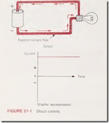
Electric current can be defined as the flow ol electrons in a circuit. Based on the electron theory, electrons flow from the negative (—) polarity to the positive ( + ) polarity of a voltage source. Direct current (DC) is current that flows only in one direction in a circuit (Figure 21- 1, p. 216). Current, in this type of circuit, is supplied from a DC voltage source. Since the polarity (negative and positive terminals) of a DC source is fixed, the current produced by it flows in one direction only. Batteries are commonly used as a DC voltage source.
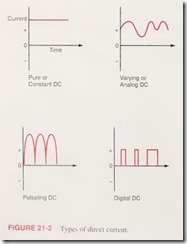
Both the voltage and polarity of the battery are fixed. When connected to a load, the current produced flows in one direction at some steady or constant value. Direct current flow need not necessarily be constant, but it must travel in the same direction at all times. There are several types of direct current and all depend upon the value of the current in relation to time (Figure 21- 2, p. 216). Pure or constant direct current shows no variations in value over a period of time and is the type associated with a battery. Both varying and pulsating direct currents have a changing value when plotted against time. Varying or analog direct current variations have no definite pattern and are associated with certain types of electrical sensor signals. Pulsating or digital direct current variations are uniform and repeat at regular intervals. These are associated with electronic DC power supplies and digital computer signals
ALTERNATING CURRENT (AC)
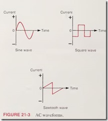
An alternating current (AC) circuit is one in which the direction and amplitude of the current flow changes at regular intervals. Current in this type of circuit is supplied from an AC voltage source. The polarity (negative and positive terminals) of an AC source changes at regular intervals resulting in a reversal of the circuit current flow. Alternating current usually changes in both value and direction. The current increases from zero to some maximum value and then drops back to zero as it flows in one direction. This same pattern is then repeated as it flows in the opposite direction. The waveform or exact manner in which the current increases and decreases is determined by the type of AC voltage source used (Figure 21- 3)
AC GENERATION
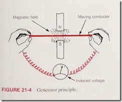
Almost all of the electric energy supplied for domestic and commercial purposes is AC. Alternating current, generated and transmitted at high voltage, is easily reduced by the use of transformers to the relatively low voltages suitable for use. Since there is no DC transformer, direct current must be generated and transmitted at practically the same voltage at which it is used. DC transmission is, therefore, limited to comparatively short distances in order to avoid unreasonably large and expensive transmission lines and power losses. The basic method of obtaining AC is by use of an AC generator (also called an alternator). A generator is a machine that uses magnetism to convert mechanical energy into electric energy. The generator principle, simply stated, is that a voltage is induced in a conductor whenever the conductor is moved through a magnetic field so as to cut lines of force. Figure 21 -4 shows the basic generator principle. As we have learned previously, electrons that are in motion set up a magnetic field around a conductor. Conversely, a change in a magnetic field around a conductor tends to set electrons in motion. The mere existence of a magnetic field is not enough; there must be some form of change in the field. If we move the conductor through the magnetic field, a force is exerted by the magnetic field on each of the free electrons within the conductor. These forces add together and the effect is that voltage is generated or induced into the conductor.
The left hand rule for a generator (Figure 21- 5) shows the relationship between the direction the conductor is moving
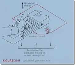 , the direction of the magnetic field, and the resultant direction of the induced current flow. When the thumb is pointed in the direction of the conductor’s motion, and the index finger in the direction of the flux, the middle finger will point in the direction of the induced electron flow. The rule is also applicable when the magnet is moved, instead of the conductor. In this case, however, the thumb must point in the direction of relative conductor motion. The amount of voltage induced in a conductor as it moves through a magnetic field depends upon:
- ■ the strength of the magnetic field; the stronger the field the more voltage induced.
- ■ the speed at which the conductor cuts through the flux; increasing the conductor speed increases the amount of voltage induced.
- ■ the angle at w’hich the conductor cuts the flux; maximum voltage is induced when the conductor cuts the flux at 90°, and less voltage is induced when the angle is less than 90°.
- ■ the leneth of the conductor in the magnetic field: if the conductor is wound into a coil of several turns, its effective length increases, and so the induced voltage will increase
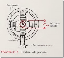
An AC generator or alternator produces an AC voltage by causing a loop of wire to turn within a magnetic field. This relative motion between the wire and the magnetic field causes a voltage to be induced between the ends of the wire. This voltage changes in magnitude and polarity as the loop is ro¬ tated within the magnetic field (Figure 21- 6). The mechanical force required to turn the loop can be obtained from various sources. For example, the very large AC generators are turned by steam turbines or by the movement of water. The voltage produced by a single loop generator is too weak to be of much practical value. A practical AC generator has many more turns of wire wound on an armature (Figure 21- 7). The armature is the movable part of the generator and is made up of a number of coils wound on an iron core. The AC voltage induced in the armature coils is connected to a set of slip rings from which the external circuit receives the voltage through a set of brushes. Electromagnets are used to produce a stronger magnetic field. The coil windings of the electromagnets are fixed or stationary and are, therefore, called stators or stator windings. Since these stator windings provide the magnetic field for the generator, they are often referred to as field coils or windings.
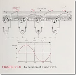
If the coil is rotated at a constant speed, the number of magnetic lines of force that are cut per second varies with the position of the coil. When the coil is moving parallel to the magnetic field, it cuts no lines of force. Therefore, no voltage is generated at this instant. When the coil is moving at right angles to the magnetic field it cuts the maximum number of lines of force. Therefore, maximum or peak voltage is generated at this instant. Between these two points the voltage varies in accordance with the sine of the angle at which the coil cuts the lines of force. The coil is shown in four specific positions in Figure 21- 8. These are intermediate positions that occur during one complete revolution of the coil position. The graph shows how the voltage increases and decreases in amount during one rotation of the loop. Note that the direction of the voltage reverses each half cycle. This is because for each revolution of the coil, each side must first move down and then up through the field.
