Electrical to audio transducers
The microphone types that we have dealt with would be of little use unless we also had transducers for the opposite direction, and such transducers have been used for even longer than microphones. Earphones were used for electric telegraphs, in which the transmitter consisted of a Morse key, so that the earphone predated the microphone by a considerable number of years. The use of both earphone and microphone in a system is attributed to Bell, in trying to develop a hearing aid for the deaf (a passionate interest that he shared with his father, and a cause that has benefited greatly from the Bell fortune) created the first working telephone system. This also laid the foundation for a telephone system in the USA that makes that of any other country seem pitifully inadequate (and very expensive).
Until the use of thermionic valves became common in radio receivers, loudspeakers were a comparatively rare sight, although the basic principles had existed for some considerable time. Without power amplification, however, the use of a loudspeaker was pointless, and this was the main reason magnetic recording lagged so much behind disc recording. The output from the mechanical disc gramophone was from a form of (non-electrical) loudspeaker and could be heard over a whole room, whereas the output of the early steel-wire recorders (Poulsen’s Telegraphone) could be heard only on earphones.
For each type of microphone, there is a corresponding earphone and loudspeaker type, and we shall look at the various types in detail. Since the basic principles of most of them have been considered under the heading of microphones, these will not be repeated. We shall, therefore, concentrate on the features that are unique to the purpose of transducing electrical signals into audio waves.
Of the two, the task of the earphone is very much simpler, and the construction of an earphone that can provide an acceptable quality of sound is very much simpler (and correspondingly cheaper) than that of a loudspeaker, as any Walkman addict will confirm. The earphone can use a small diaphragm, and ensure that the sound waves from this diaphragm are coupled directly to the ear cavity. The power that is required is in the low milliwatt level, and even a few milliwatts can produce considerable pressure amplitude at the eardrum – often more than is safe for the hearing. The conditions of use are, in other words, strictly defined, and the designer can concentrate on reducing resonances and increasing linearity in the certain knowledge that the effect will be noticeable.
The loudspeaker designer has much more of an uphill task. A loudspeaker is not used pressed against the ear, so that the sound waves will be launched into a space whose properties are unknown. In addition, the loud- speaker cannot be used alone but has to be housed in a cabinet whose resonances, dimensions and shape will considerably modify the performance of
the loudspeaker unit. The assembly of loudspeaker and cabinet will be placed in a room whose dimensions and furnishing are outside the control of the loudspeaker designer, so that a whole new set of resonances and the presence of damping material must be considered. One designer has said that if we had not known loudspeakers before now, it is unlikely that we would even consider trying to make them today, just as we would have banned the use of steam if environmentalists had been around in the 19th century. Fortunately, human beings show a marked reluctance to return to caves after tasting better things.
The transducer of a loudspeaker system is sometimes termed the ‘pressure unit’, and its task is to transform an electrical wave, which can be of a very complex shape, into an air-pressure wave of the same waveform. To do this, the unit requires a motor unit, transforming electrical waves into vibration, and a diaphragm that will move sufficient air to make the effect audible. The diaphragm is one of the main problems of loudspeaker design, because it must be very stiff, very light and free of resonances – an impossible combination of virtues. Practically every material known has been used for loudspeaker diaphragms at some time, from the classic varnished paper to titanium alloy and carbon fibre, and almost every shape variation on the traditional cone has been used.
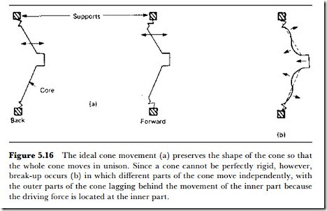
The main cone problem is break-up. If the cone is to be able to handle low frequencies, it must have a large area. At high frequencies, however, there will be waves on the cone itself, so that different parts of the cone move in different directions (Figure 5.16). This causes the waves from the different parts of the cone to interfere with each other, considerably modifying the response. The usual solution to this problem is to use more
than one driver unit and divide the electrical signal into low and high frequency components fed to the appropriate units. This is, after all, reason- ably justified because few musical instruments produce a full range of sound frequencies and there is no reason why a single loudspeaker should. The low-frequency units are known as woofers and the upper frequency units as tweeters, but this attractive terminology is abandoned in the mid range where the units are simply termed mid-frequency units. The few loud- speaker designs that have achieved high-quality results with a single diaphragm, however, are among the best known.
• One solution to the problem of break-up is to use separate loudspeakers for different parts of the sound band, typically one unit for the 20-120 Hz range (a woofer), another for the frequencies above 5 kHz (a tweeter), and a third for the intermediate frequencies.
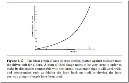
The efficiency of loudspeakers is notoriously low, around 1%, mainly because of the acoustic impedance matching problem for low frequency signals. In simple terms, most loudspeakers move a small amount of air with comparatively large amplitude, whereas to produce a sound wave effectively they ought to move a very large amount of air at comparatively low amplitude. This mismatch can be remedied to some extent by housing the loudspeaker in a suitable enclosure, but the only type of enclosure that increases the overall efficiency is the exponential horn (Figure 5.17). The sheer size of the horn and the rigid dense construction that is needed make this an unacceptable solution for all but the most avid listeners, one of whom had the foundations of his house cast so that they form an exponential horn shape. Nothing less really suffices, because it is only when the listening end of a horn is about 16 feet square that the benefits of horn-loading become really noticeable. The effect is still noticeable even for small linear horns, however, and the astonishing effect of bringing up the small end of a horn to a Walkman earphone is something that has to be heard to be believed.
• The factor that, more than any other, determines loudspeaker efficiency is the need for a broadband response, and if a loudspeaker is needed to cover only a small band of high frequencies it can be designed to achieve comparatively high efficiency levels. An example is the piezoelectric tweeter used in smoke alarms, which develops a large amplitude of high- pitched sound with only the power of a 9 V battery.
THE MOVING-IRON TRANSDUCER
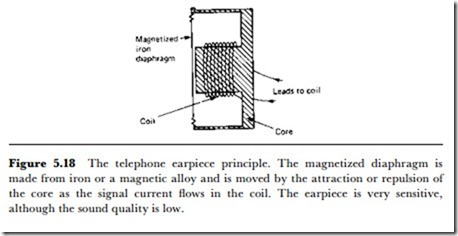
The first type of earphone, as applied to the early telephones, was a moving- iron type, and this principle has been extensively used ever since. As applied to the telephone, the earphone uses a magnetized metal diaphragm (Figure 5.18) so that the variation of magnetization of the fixed coil will ensure the correct movement of the diaphragm. Without this fixed magnetic polarization, the diaphragm frequency would be twice the frequency of the electrical signal. Earphones of this type are very sensitive, but the sound quality is very poor because of the comparatively stiff diaphragm that causes unavoidable resonances.
Miniature moving-iron earphones are still in use, particularly where sound quality is not of the highest importance, but the principle has died out as far as loudspeakers are concerned. At one time, moving-iron loud- speakers, which were virtually earphone units with a cone attached, were used, but these were soon replaced by the moving-coil type that provided
noticeably better sound quality. The sound of the early loudspeakers has been aptly described as a ‘mellow bellow’, and this is no longer acceptable except inside cars. Listeners are, thanks to FM radio, gradually learning that the high frequencies, particularly of speech, carry the major amount of the acoustic information and that emphasis of lower frequencies is pointless. Some day, directors of TV dramas will also learn that background noise can easily obscure the dialogue that makes a play intelligible.
THE MOVING-COIL TRANSDUCER
The moving-coil principle as applied to loudspeakers and earphones has been extensively used, and the vast majority of loudspeakers use this principle. The use of moving-coil earphones has been less common in the past, but these are now in widespread use thanks to the miniature cassette player vogue. As applied to earphones, moving-coil construction permits good linearity and controllable resonances, since the amount of vibration is very small and the moving-coil unit is light and can use a diaphragm of almost any suitable material.
The use of moving-coil drivers with cones to form loudspeakers is by no means so simple. One problem of all loudspeakers is that the unit that reproduces the low frequencies needs a very freely suspended cone and must be able to reproduce large amplitudes of movement. This amplitude of movement can be a centimetre or more, and it is very difficult to ensure that the magnetic flux density around the moving coil is uniform over this distance. The design of the magnetic circuit calls for a large magnet and a large core, and a shape that is computed to provide the best available linearity of flux density. In addition, there is a conflict between making the coil and cone very freely suspended and yet maintaining the position of the coil concentric in the core of the magnet.
The magnets of modern moving-coil units are invariably permanent magnets, often using quite exotic alloys. At one time, moving-coil loudspeakers, known as ‘dynamic’ loudspeakers, used an electromagnet to provide the magnetic field, but this vogue was short-lived because of the demands it made on the power supply of the radio receiver that used it.
At the other end of the frequency scale, there is no requirement for large amplitudes of movement, and the main problems are of resonance and cone break-up. Metal cones are often used with success, but a large number of successful designs of loudspeaker systems use moving coil units only for the lower and mid frequencies, with other types used for the highest frequencies.
A variation of the moving-coil principle that has been successfully used for earphones is the electrodynamic (or orthodynamic) principle. This uses a diaphragm that has a coil built in, using printed circuit board techniques. The coil can be a simple spiral design, or a more complicated shape (for
better linearity), and the advantage of the method is that the driving force is more evenly distributed over the surface of the diaphragm. This avoids break-up, and allows the use of a much more flexible diaphragm than would be possible otherwise. Headphones based on this principle have been very successful and of excellent quality.
RIBBON LOUDSPEAKERS
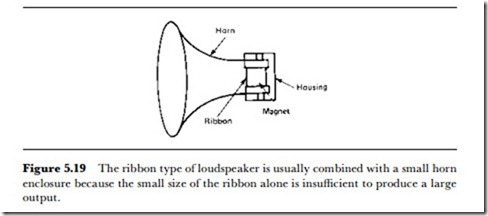
The ribbon principle, already dealt with under the heading of microphones, is also used to provide loudspeaker action. The moving element of a ribbon loudspeaker is necessarily small, and for that reason, the unit is a tweeter rather then a full-range type. The ribbon construction, however, offers a very directional response and can be built into a small horn type of enclosure (Figure 5.19), which makes it a very efficient transducer compared to others. Ribbons of about 5 cm long, corrugated along the length for stiffness, are used, and because the impedance is very low (a fraction of an ohm) matching transformers are usually built into the loud- speaker. With conventional construction, the ribbon tweeter can handle frequencies from 5 kHz upwards, but a more elaborate design can allow this range to be extended down to about 1 kHz.
Wide-range multi-ribbon units are also feasible, but in a very different size (and price) category. The commercially available types use three units, of which the bass unit is very large, and requires its own amplifier to supply about 100 W driving power.
PIEZOELECTRIC LOUDSPEAKERS
The piezoelectric principle has been used in the manufacture of tweeters, for which it is reasonably suited if the problems of resonance can be dealt
with. Such tweeters can be of quite high efficiency and are widely used in applications ranging from smoke detectors to computer modems.
The piezoelectric principle has also been used for earphones in the form of piezoelectric (more correctly pyroelectric, since the electrical parameters are temperature sensitive) plastics sheets, which can be formed into very flexible diaphragms. The effect of applying a voltage between the faces of such a diaphragm is to make the dimensions shrink and expand as a waveform is applied. This in turn can be converted into a movement that will move air by shaping the diaphragm as part of the surface of a sphere. This can be done, for example, simply by stretching the material over a piece of spherical plastic foam. The moving mass is very small and sensitivity is high, with no need for a power supply. The linearity that can be obtained depends on the surface shape as well as on the piezoelectric characteristics.
CAPACITORTRANSDUCERS
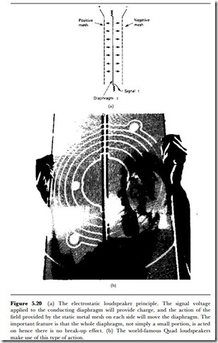
The possibility of constructing earphones or loudspeakers along the lines of a capacitor microphone has existed for a long time, but the practical difficulties have been satisfactorily resolved by only two designs: the Quad (Figure 5.20) and the Magna-Planar wide-range electrostatic loudspeakers. The main problem, initially, was that using a single-ended design analogous to a capacitor microphone provides very poor linearity. The breakthrough was the principle, due to Peter walker, of a diaphragm which had a signal voltage applied to it and which faced a sheet of conducting material at a high voltage on each side. The system has also been used in earphones that, despite the need to provide a high polarizing voltage for the plates, have been very popular and of outstanding audio quality.
The advantage that makes the electrostatic loudspeaker principle so attractive is that the driving effort is not applied at a point in the centre of a cone or diaphragm, but to the whole of a surface that can be large in area. There is, therefore, no break-up problem, since all parts of the diaphragm are driven, and so a single unit can handle the whole of the audio range. Resonances can present a negligible problem, due to the overall drive, and no special enclosure other than is required for electrical safety and mechanical rigidity will be necessary. The original Quad design has now been in production for over 21 years and, although recently rede- signed, still follows the original principles and provides outstanding quality, particularly for concert-hall performances.
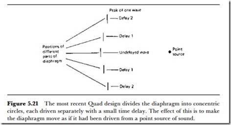
The most recent design uses the ‘point-source’ principle, achieved by driving the diaphragm as a set of concentric circles that are not in phase. In this way (Figure 5.21), the sound wave that is created appears to come from a point behind the diaphragm. The practical effect of this is to make
the sound appear to be independent of the loudspeaker in a way that is quite remarkable as compared to moving-coil units.
The electret principle has not been used to date for loudspeakers, but earphones have been constructed which follow the basic capacitor type of design but using an electret to provide the fixed charge. These are claimed to give a performance that approaches that of the best electrostatic types, but at a much lower cost and free of the need to supply a polarizing voltage.
ULTRASONIC TRANSDUCERS
Although loudspeakers and microphones may use similar operating principles, the differences between receiving a sound wave and generating it are sufficient to make the actions interchange only very poorly. A loudspeaker can generally be used as a microphone, but as an insensitive and low- quality microphone. A microphone can be used as an earphone with some success, but is not suitable as a loudspeaker because it is not designed to handle the amount of power that is needed.
By contrast, the transducers that we use for ultrasonic waves are usually of a type that is almost totally reversible. The transducers that are used for sending or receiving ultrasonic signals through solids or liquids can operate in either direction if required. For ultrasonic signals sent through the air (or other gases), the transducers are used with diaphragms and in enclosures that can make the application more specialized, so that a transmitter or a receiver unit has to be used for its specific purpose.
The important ultrasonic transducers are all piezoelectric or magnetostrictive, because these types of transducers make use of vibration in the bulk of the material, as distinct from vibrating a motor unit which then has to be coupled to another material. The magnetostrictive principle is not generally applied in the audio frequency range. Magnetostriction is the change of dimensions of a magnetic material as it is magnetized and demagnetized, and the most common experience of the effect is in the high- pitched whistle of a TV receiver, caused by the magnetostriction of the line output transformer. Several types of nickel alloys are strongly magnetostric- tive, and have been used in transducers for the lower ultrasonic frequencies, in the range of 30-100 kHz.
A magnetostrictive transducer consists of a magnetostrictive metal core on which is wound a coil. The electrical waveform is applied to the coil, whose inductance is usually fairly high, so restricting the use of the system to the lower ultrasonic frequencies. For a large enough driving current, the core magnetostriction will cause vibration, and this will be considerably intensified if the size of the core is such that mechanical resonance is achieved. The main use of magnetostrictive transducers has been in ultra- sonic cleaning baths, as used by watchmakers and in the electronics industry.
The piezoelectric transducers have a much larger range of application although the power output cannot approach that of a magnetostrictive unit. The transducer crystals are barium titanate or quartz, and these are cut so as to produce the maximum vibration output or sensitivity in a given direction. The crystals are metallized on opposite faces to provide the electrical contacts, and can then be used either as transmitters or as receivers of ultrasonic waves. The impedance levels are high, and the signal levels will be millivolts when used as a receiver, or a few volts when used as a transmitter.
• Two important parameters of an ultrasonic transmitter/receiver are beam spread and target angle. The beam spread is the area in which a round wand will be sensed if it is passed through the beam. This defines the maximum spreading of the ultrasonic sound from the transducer. The target angle measures the maximum amount by which the target can be tilted and still be detectable by an ultrasonic transducer.
Although piezoelectric transducers are used in ultrasonic cleaners, their main applications are in security devices and signal processing. An ultrasonic transmitter in air can ‘fill’ a space (such as a room or a yard) with a standing-wave pattern, and a receiver can detect any change in this pattern that will be caused by any new object. Ultrasonic units cannot necessarily distinguish between a cat and a cat burglar, however. For signal processing, a radio-frequency signal can be converted to an ultrasonic signal by one transducer and converted back by another, using the ultrasonic wave path, usually in a solid such as glass, to create a delay. This use of an ultrasonic delay was at one time essential to the PAL colour TV system that is used in most of western Europe, but has now been replaced by digital delays.
Ultrasonic transducers are very widely used in security applications for detecting objects, and some systems can detect up to a range of 12 m, and by suitable selection of transducers the angle of coverage can be either wide or narrow. Target material is not critical, so that any surface capable of acoustic reflection can be detected, including liquids and soft or porous materials. Distance measuring can also be achieved with an accuracy of around 0.05% of range.
• Ultrasound waves can also be filtered by mechanically shaping the solids along which they travel, and this is the basis of surface wave filters.
INFRASOUND
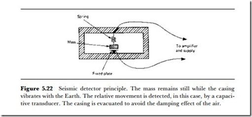
The wave frequencies below 20 Hz are not so extensively used as the ultrasonic frequencies, but the sensing of these frequencies is a matter of some importance. The vibrations of the Earth that are accompanied by earthquakes are in the very low-frequency region, and are termed seismic waves. Transducers for seismic waves must be capable of very low-frequency response, which rules out the use of piezoelectric transducers. Most seismic transducers work on the principle of using a suspended mass to operate a transducer of the capacitive or inductive type, such as the example in Figure 5.22. The principle here is that the vibrations of the Earth will move the casing, leaving the suspended mass at rest, and that the relative motion between the supports and the mass will produce the output.
![]() The other natural source of very low-frequency vibrations is the communication of whales, and the signal strength is often enough to permit a piezoelectric type of transducer to be used. A large diaphragm is mechanically coupled to the piezoelectric crystal and the output from the crystal is connected to a MOSFET amplifier, with a chopper stage (see Chapter 12) used for the main amplification. The usual technique with these signals is to tape-record them with a slow-running tape, and replay at a higher speed to make it easier to display (and hear) the waveforms.
The other natural source of very low-frequency vibrations is the communication of whales, and the signal strength is often enough to permit a piezoelectric type of transducer to be used. A large diaphragm is mechanically coupled to the piezoelectric crystal and the output from the crystal is connected to a MOSFET amplifier, with a chopper stage (see Chapter 12) used for the main amplification. The usual technique with these signals is to tape-record them with a slow-running tape, and replay at a higher speed to make it easier to display (and hear) the waveforms.
