Conventional print head service techniques
A PRINT HEAD IS THAT PART OF A PRINTER THAT DELNERS
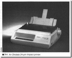
a permanent image to the page surface. The image might be a let ter, number, or symbol (in the case of a character printer). But it might also be a pattern of dots that come together to form any type of characters or graphic images. As discussed in Chapter 3, there are tlu·ee conventional technologies used to deliver perma nent images: impact, thermal, and ink jet. The remainder of the printer, from its ECU to its paper feed system, is designed to ac commodate the partic ular print head technology (figure 7-1). This chapter identifies and offers solutions for common print head problems. Chapter 11is entirely devoted to EP plinter service.
Dot-matrix impact print heads
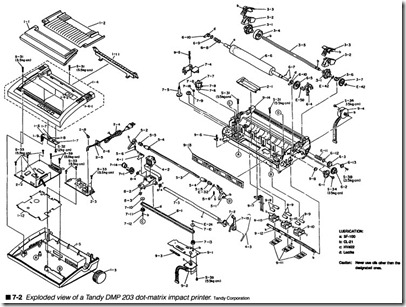
A complete dot-matrix impact (DMI) printer assembly is illustrated in figure 7-2. Individual print wires are assembled into a die cast metal housing (the print head itself is marked 4-2). There might be 7, 9, or 24 print wires in the head depending on the sophistication of the particular printer. The print head is mounted on a carriage (shown as 8-2) that is carried back and forth along a rail (marked 7-3) by a belt (marked 8-1), which is driven by a motor (shown as 9-2). The print head is connected to the ECU (marked 2-2) through a long, flat, flexible cable, called the print head cable.
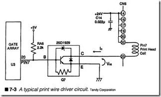
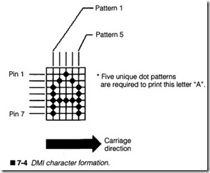
When the host computer sends a character to be printed, a series of vertical dot patterns representing that character (in its selected font and size) are recalled from the printer’s permanent memory. The ECU sends each dot pattern in turn through a series of print wire driver circuits. A typical print wire driver circuit is shown in figure 7-3. It is the driver circuits that amplify digital logic signals from main logic into the fast, high-energy pulses needed to flre a print wire. As a pulse reaches the firing solenoid, it creates an in tense magnetic fleld, which shoots its print wire forward against the page. After the pulse is complete, a spring (not shown in figure 7-3) pulls the print wire back to its rest position. Figure 7-4 shows a typical printing sequence for a letter “A.”
Impact heating problems
One of the major problems with impact printing is the eventual buildup of heat. The substantial amount of current needed to fire a solenoid is mostly given up as heat that must be dissipated by the print head housing. Under average use, the metal housing will dis sipate heat quickly enough to prevent problems. Heavy use, how ever, can cause heat to build faster than it dissipates. This happens most often when printing bit-image graphics where many print wires might fire continuously. Excessive or prolonged heating can cause unusual friction and wear in print wires. In extreme cases, uneven thermal expansion of hot pins within the housing might cause them to jam or bend.
To combat the buildup of heat, impact print heads are cast with a series of heat sink fins. If you look at the print head in figure 7-2 closely, you can see the heat sink fins depicted. In order for heat sink fins to be effective, they must be exposed to the open air; buildup of dust, dirt, and paper debris will prevent heat from vent ing to the air. When inspecting an impact print head, always make sure that the heat sink flns are clear.
Evaluating the print head
The first step in all diagnosis is examination. In the case of print head testing, you should print a sample page that will place the print head under a certain amount of stress. Now, it is certainly possible to discern glaring problems while printing ordinary text, but to really push the print head’s capabilities, the printer should generate a demanding graphic. You can use the companion utility PRINTERS to generate a print head test pattern, the large black rectangle shown in figure 7-5. By observing inconsistencies in the resulting image, you can make an accuraLe determination of the print problems. Of course, if you have other utilities that will gen erate similar results, feel free to use them as well.
Troubleshooting impact print heads
Generally speaking, impact print heads are some of the most reli able electromechanical devices available. With life expectancies easily exceeding 30 million characters, each print wire is rated for hundreds of millions of operations. In spite of their reliability, how ever, operating practices and environments will affect the print head’s service life. Reliable prinL head pe rf ormance is also related to routine maintenance; neglected maintenance will typically re sult in print problems.
Symptoms
Warning: The impact print head can become extremely hot dur ing the printing process. Be sure to allow at least 10 minutes of idle time for the print head to cool before attempting any service.
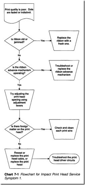
Symptom 1 Print quality is poor. Dots appear faded or indistinct. All other operations appear normal. Refer to Chart 7-1. The Print Head Test pattern should yield a solid black rectangle. In actual practice, the rectangle drawn by an impact print head will not be
absolutely homogeneous, you will be able to discern slight tone differences in each pass, but the print should be sharp and the color tone should be consistent. If the print is excessively light, or there are patches of light and dark areas, you should begin by carefully examining the ribbon. It should be reasonably fresh and it should advance normally while the carriage moves back and forth. A ribbon that is not advancing properly (if at all) might be caught or jammed internally, so install a fresh ribbon and retest the printer. If the ribbon still does not advance properly, trou bleshoot the printer’s ribbon advance mechanics as specified in Chapter 10. A fresh ribbon might improve image quality, but that will fade again quickly if the ribbon does not advance.
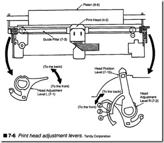
Examine your print head spacing next. Most printers are designed with one or two small mechanical lever adjustments that can alter the distance between print head and platen by several thou sandths of an inch (such as the level shown in fJgure 7-6). This ad justment allows print intensity to be optimized for various paper thicknesses, and can be adjusted to keep the print head perfectly parallel to the platen. If the print head is too far away from the platen for your current paper thickness, the resulting print might appear light or faded. When there are two adjustments (as in fig-ure 7-6), adjust the right lever so that there is no smudging or missed dots along the right side of the image, then adjust the left lever so that there is no smudging or missed dots along the left side of the image. If spacing is already close or nonadjustable, turn your attention to the print head itself.
Turn off and unplug the printer, then check each print wire in the head assembly. Print wires should all be free to move, sliding in and out without restriction, except for mechanical tension from the return spring. Keep in mind that you will probably have to re move the print head from its carriage assembly. Over an extended period of time, a combination of paper dust and ink form a sticky glue that can work its way into each print wire. As this substance dries, it can easily restrict a wire’s movement or jam it all together. If you fmd a tremendous buildup of foreign matter, wipe off each wire as gently as possible. Use a stiff cotton swab dipped lightly in alcohol or light-duty household oil. Do not use harsh chemical sol vents! Finally, wipe down the front face of the print head with a soft, clean cloth. Once all wires are moving freely again (and any loosened glue has been removed), replace the print head and retest the printer. If you do remove the print head for cleaning, be sure to readjust the head spacing lever(s) to keep the head paral lel to the platen.
Another possible problem area might be in the print head cable it self. If the cable (especially the ground) connections are loose or marginal, the increased resistance in the print wire circuits might lighten the print. Try reseating the print head cable one or more times. If this does not help, try replacing the print head cable. If problems continue (or the cable cannot be replaced without ex changing the print head), try a new print head assembly.
Finally, you should remember that it is the print head driver cir cuitry that supplies energy necessary for print wire operation. There could be a loss of solenoid driving voltage or some other defect in your drivers. Chapter 9 details driver troubleshooting procedures.
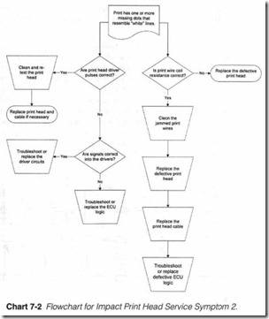
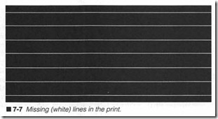
Symptom 2 Print has one or more missing dots that resemble “white line(s).” This also takes place during a self test or Test Page. Refer to Chart 7-2. This type of symptom generally resem bles the illustration in figure 7-7. The white line(s) should be equally noticeable in text as well as graphics. Assuming that all other operations of the printer are correct, a loss of one or more dot rows suggests that the corresponding print wire(s) will not fire. In most cases, this is due to a fault in the print head, the print head cable, or the corresponding driver circuitry. However, you will need to explore each step in order to determine the point of failure.
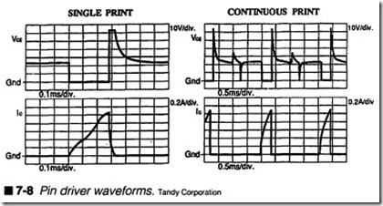
If you have an oscilloscope available, you can use the oscilloscope to measure the driving pulses being sent to the print head, which should appear similar to those shown in figure 7-8. The schematic fragment shown in figure 7-9 illustrates a typical ECU driver-to print head configuration. If you see driver pulses being sent to a pin, but the corresponding pin is not firing, chances are good that the print wire is jammed (or has failed completely). You can then proceed to shut off and unplug the printer, then clean each print wire carefully to remove any accumulations of buildup. Reinstall the cleaned print head and retest the printer. If the problem per sists, replace the print head and print head cable.
If the expected pulse signal(s) are missing, it means that the of fending print wires are not receiving driver signals; this is a sign of driver circuit failure in the ECU. As you see in figure 7-9, each print wire is operated by its own discrete driving transistor. You can then use your oscilloscope to check the logic signal driving the suspect transistor. If the logic signal is present on the transistor’s base, but the output signal on the transistor’s collector is missing, the transistor is faulty and should be replaced. If your inspection reveals that the logic signal itself is missing, then the ASIC in the ECU that generates the logic outputs is defective and should be replaced. From a practical standpoint, it might not be possible for you to obtain replacement components or replace those compo nents with the soldering tools you have available. Inthat case, you should simply replace the ECU outright because it typically con tains all of the logic and driver circuitry.
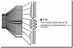
So what if you don’t happen to have an oscilloscope handy? Well, you can shut off and unplug the printer, then use your multirneter to measure the resistance between the 24-V ground and each pin ter minal, as shown in figure 7-10. You should read approximately 19.5 Q between ground and any pin (the resistance of a solenoid coil). If you read an open or short circuit instead, the solenoid is defective, and the entire print head must be replaced. When replacing a print head, you should also replace the print head cable if possible.
If all of the solenoids check out properly, then you might be facing one or more jammed print wires, so remove the print head and carefully clean the face (and the print wires if possible). If any of the wires appear jammed, or do not extend to their full length (even after a thorough cleaning), the pin(s) might be damaged, in which case you should replace the print head and cable. After any accumulations of buildup have been removed and the unit is dry, reinstall the print head and retest the printer. If problems persist, there might still be a fault in the print wire itself, the print head ca-
ble, or the ECU. Because you have already demonstrated that the print solenoids are intact, check the continuity across the print head cable. If any connections are broken or intermittent, replace the print head cable. Otherwise, replace the ECU outright (which\.\rill effectively replace the print head logic and driver circuitry). In the unlikely event that you have not yet corrected the problem, the only remaining possibility is that one or more pins in the print head have actually broken. In that case, try a new print head.
Symptom 3 Print appears “smeared ” or exceedingly dark. All other operations appear normal. Unfortunately, this type of problem cannot be detected by reviewing a dark graphic. Instead, smeared or extremely dark print is best discovered with a textured graphic or text (such as the printer’s self test or Print Test Page feature in PRINTERS), as shown in figure 7-11. However, smeared print is relatively easy to correct.
One of the most likely reasons for smeared print in an impact printer is that the print head is too close to the platen. When the head is too close, the prin t wires might not have enough time to re tract before the carriage moves, thus smearing the print. The an swer is to retract the print head a bit using the position adjustment lever(s), sho·wn in figure 7-6.
Another possible problem can occur when buildup accumulates on and in the print head. Foreign matter can affect the dimensions and stroke of the print wires. It can also jam the print wires in an extended position and prevent them from retracting before the carriage moves, again smearing the print. Tum off and unplug the printer. You can then remove the print head and clean the face and print wires. If problems continue at this point, chances are good that your print head is defective, or fouled with build up so badly that cleaning is not effective. Try replacing the print head.
Symptom 4 Printer does not print under computer control. Oper ation appears correct in self-test mode. Before you disassemble the printer, take a moment to check its “on-line” status. There is almost always an indicator on the control panel that is lit when the printer is selected. If the printer is not selected (on-line), then it will not receive information from the computer, even if everything is working correctly.
A printer can be off-line for several reasons. Paper might have run out, in which case you will have to reselect the printer explicitly after paper is replenished. Even the simplest printers offer a vari ety of options that are selectable through the keyboard (e.g., font style, character pitch, line width, etc.). However, you must often go off-line in order to manipulate those functions, then reselect the printer when done. You might have selected a function incor rectly, or forgotten to reselect the printer after changing modes. Also consider software compatibility. If you are using a “canned” software package, make sure that its printer driver settings are configured properly for your particular printer.
Check your communication interface cable next. It might have be come loose or unattached at either the printer or computer end. If this is a new or untested cable, make sure that it is wired correctly for your particular interface. An interface cable that is prone to bending or flexing might have developed a faulty connection, so dis connect the cable at both ends and use your multimeter to check cable continuity. If this is a new, homemade cable assembly, double check its construction against your printer and computer interface diagrams.
Double check the printer’s DIP switch settings or set-up configu ration. DIP switches are often included in the printer to select certain optional functions such as serial communication format, character sets, default character pitch, or automatic line feed. If you are in stalling a new printer, or you have changed the switches to alter an operating mode, it might be a faulty or invalid condition. DIP switches also tend to become unreliable after many switch cycles. If you suspect an intermittent DIP switch, rock it back and forth several times, then retest the printer.
When everything checks out, you will have to disassemble the printer and troubleshoot its interface circuits and main logic. Use the troubleshooting procedures provided in Chapter 9.
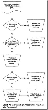
Symptom 5 Print head moves back and forth, but does not print (or prints only intermittently). This also takes place during a self-test or test patterns. Refer to Chart 7-3. If the print appears to gradu ally fade in and out, check your ribbon frrst. Make sure that it is in stalled and seated properly between the platen and print head. If the ribbon has dislodged from the head path or is totally ex hausted, no ink will be deposited on paper. Ifthe ribbon is in place, make sure that it advances properly as the carriage moves. A rib bon that does not advance properly might be caught or jammed in ternally, so install a fresh ribbon and retest the printer. If the ribbon still fails to advance, troubleshoot the printer’s ribbon ad vance using procedures in Chapter 10.
If the print appears to cut in and out suddenly, suspect an inter mittent connection. Intermittent connections in the print head ca ble or within the print head itself can lead to highly erratic head operation. A complete cable break can shut down the print head entirely, especially if the break occurs in a common (ground) conductor. Unplug the printer and use your multimeter to check con tinuity across each conductor in the print head cable. You might have to disconnect the cable at one end to prevent false readings. Replace any print head cable that appears defective.
You should check the printer’s power supply outputs next. Apply printer power and measure the print head driver voltage (usually+12 or +24 Vdc). If driver voltage is low or nonexistent, drivers will not produce enough energy to fire a print wire. Marginal sup ply outputs can result in intermittent operation. Check your cir cuit connections. If you find that the power supply voltage is low or erratic, troubleshoot the power supply using the procedures of Chapter 8. If the power supply is integrated into the ECU and must be replaced, you will have to replace the entire ECU outright.
Your trouble could exist in the print head itself. Turn off and un plug the printer, then disengage the print head from its carriage. Use your multimeter on a low resistance scale to measure there sistance of each frring solenoid as in figure 7-10. If the head is com pletely inoperative, the common lead might be intermittent or open. If you fmd any open or shorted firing solenoid, replace the print head mechanism.
If your print head is still intermittent or totally inoperative, chances are that there is a serious problem in the driver circuits; either the print head logic or drivers are intermittent or has failed entirely. If you have an oscilloscope, you can troubleshoot the print head signals through the ECU; the point at which the signals disappear is the point of failure. If you do not have an oscilloscope handy, replace the ECU.
Thermal dot-matrix print heads
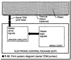
Thermal dot-matrix (TDM) print heads substitute print wires with individual solid-state dot heaters. Much like DMI print heads, a se rial TDM head, as shown in figure 7-12, is assembled as a vertical column of seven or nine dot heaters. The head is mounted on a carriage, which carries it back and forth across the page. Every dot can be fired independently by logic pulses amplified with driver circuits. Thermal line-print heads are stationary devices that hold a single horizontal row of dot heaters, one for every possible dot in a row. Figure 7-13 illustrates a block diagram for a typical line print head. Because each dot heater in a line consumes relatively little power, the driver circuits for a line-print head are usually fab ricated into the head assembly itself.
A “serial” TOM print head works almost identically to an impact print head. When a character is received from the host computer, a series of vertical dot patterns representing that character (in cluding font and size) are recalled from the printer’s permanent memory. Each dot pattern is sent out in tum, where they are am plified by driver circuits and finally delivered to the print head. Drivers convert the digital information developed in main logic into the high-energy pulses required to fire dot heaters. As a pulse reaches a dot heater, it causes a sudden, large temperature rise. This localized heat is used to discolor corresponding points on thermally sensitive paper, or melt corresponding points of plastic ink on a thermal ribbon.
“Line-print” heads are more sophisticated, and depend much more on ECU’s processing power. After a complete line of characters is sent from the host computer (a “line” ends when the printer sees a “carriage return” or “line feed” character), ECU logic translates the entire line into a series of horizontal rows that span the paper’s width. A horizontal row is printed onto thermally sensitive paper (or through a thermal ribbon), paper advances a fraction to the next adjacent row, then another row is printed. This continues un til the entire line is complete. If a new row of characters is received, the process will repeat. While the circuitry needed to implement a line head assembly is a bit more complex than that needed for a se rial head, the line head architecture eliminates the need for a car riage transport system.
Thermal contact problems
In order for a thermal print head to function at all, it must be in contact with the heat-sensitive paper surface (or the thermal trans fer ribbon). The problem here is that contact pressure must be within a fairly narrow margin; to ensure proper printing, adequate heat must be applied for some minimum period of time. Ifthe print head is not applying enough force, the resulting print will likely ap pear faint or fuzzy where dots form improperly. Make sure that there are no accumulations of dirt or debris that are forcing the print head away from the paper. If the print head is applying too much force, the print head might have trouble moving smoothly. This can result in unusually dark or smudged print. In extreme cases, the paper might not advance properly. When checking print problems on a thermal printer, always wipe the face of the print head to remove dust and foreign matter, then make sure that the print head contact pressure is within acceptable limits. Thermal print heads are also fragile, static-sensitive devices, so use caution when handling them.
Evaluating the print head
The first step in all diagnosis is examination. In the case of thermal print head testing, you should print a sample page, which will place the print head under a certain amount of stress. You can dis cern glaring problems while printing ordinary text, but to really push the print head’s capabilities, the printer should generate a demanding graphic. You can use the companion utility PRINTERS to generate a print head test pattern, such as a test page, or the large black rectangle shown in figure 7-5. By observing inconsis tencies in the resulting image, you can make an accurate determi nation of the print problems. Of course, if you have other utilities that will generate similar results, feel free to use them as well.
Troubleshooting thermal print heads
Thermal print heads are uniquely self-contained devices. Unlike impact and ink jet technologies, there is nothing to maintain; ther mal print heads are sealed devices. Even the more complex line heads that incorporate driver circuitry are little more than large integrated circuits. They cannot be recycled, rebuilt, or refur bished. When any part of the print head fails or wears out, the en tire print head must be replaced. The only two operations that you can safely perform on a thermal print head are cleaning and con tact adjustment.
Symptoms
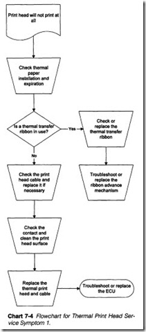
Symptom 1 Print head will not print at all. All other functions ap pear correct. Refer to Chart 7-4. Before starting any work on the printer, take special notice of the thermal paper or transfer ribbon. If your thermal printer uses heat-sensitive paper, be sure that the paper supply is fresh and inserted with the heat-sensitive side (usually the shiny side) facing the print head. If the paper is in serted backward (dull side showing), no print will be generated, even if everything is working properly. Keep in mind also that ther mal paper has a limited working life, so if it is very old or discol ored, print might appear faded, or not appear at all. Transfer ribbons deserve just as much attention. If your printer uses a ther mal transfer ribbon, be sure that it is installed and seated properly, and check that there is still fresh ribbon available in the cartridge. Replace the ribbon cartridge if it is exhausted.Inspect your print head cable next. A loose or broken cable can easily disable a print head, especially if the fault is in a common conductor. Turn off and unplug the printer, then use your multi meter to measure continuity across the cable. You might have to disconnect the cable from at least one end to prevent false read ings. Wiggle the cable while checking continuity to stimulate any intermittent connections. Replace any defective print head cable.
Check your serial print head for any obvious faults, such as cracks, or burned or discolored areas. Remove the print head from its car riage and observe its face closely. Clean away any accumulation of dust or debris that might be formed on the print head. Remember that the print head must be in contact with the ribbon or paper for proper heat transfer to take place. Any dust or debris that builds up on the face can push the head just far enough away to interfere with heat transfer. Wipe the face with a clean, soft cloth dampened with ethyl alcohol. Replace the print head assembly and print head cable, especially if they show signs of excessive surface wear. Line print heads contain a substantial amount of logic and driver cir cuitry built right into its assembly. If a line-print head fails to work, it might have suffered an internal multiplexer or driver failure, so try replacing the print head as well. If the problem persists, re place the printer’s ECU.
Symptom 2 Printer does not print under computer control. Opera tion appears normal in its self-test mode. Check your printer’s “on line” status before performing any service procedures. Most control panels provide an indicator that displays the printer’s on-line (se lected) status. If your printer is not on-line, it will not receive information from the computer, even if everything is working properly.
A printer can go off-line for several reasons. A printer will go off line automatically if paper is exhausted. That will inhibit a printer until paper is replenished and the printer is reselected manually. You must often take a printer off-line in order to set most functions from the control panel (e.g., font style, character pitch, line width, etc.). After functions are manipulated, the printer must be rese lected manually. If you forget to reselect the printer, or you have selected an incorrect mode, the printer might remain off-line. Fi nally, you should consider software compatibility. If you are using a “canned” software package, make sure that the correct printer driver is installed.
Inspect your communication interface cable next. It might have become loose or detached at one end. If this is a new or untested cable, make sure that it is wired correctly for your particular in terface. Cables that are pron e to bending or flexing might develop faulty connections, so disconnect the cable at both ends and use your multim eter to check cable continuity. Refer to interface in formation for your printer and computer to verify cable wiring.
Examine any DIP switch configurations in your printer. DIP switches are commonly used to change optional settings, such asserial communication formats, character sets, or automatic line feed. If this is a new installation or you have changed operating modes in any way, the selection might be faulty. DIP switches also have the tendency to become unreliable after many switch cycles. If you suspect a faulty switch , rock it back and forth several times, then retest the printer. If problems persist at this point, the printer might have a defective interface circuit, or trouble in its main logic. Follow the troubleshooting procedures in Chapter 9.
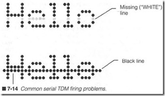
Symptom 3 Print contains one or more missing (white) or consis tent black lines through the print. This also takes place during self test or test pages. When one or more dot heaters fail to fire, you ‘vill see lines through the print that are devoid of any dots. This gives the optical illusion of “white” lines as shown in figure 7-14, and can be reviewed even better with a dark graphic, such as a Print Head Test. Although figure 7-14 shows a horizontal line as the result of a print head fault, the missing line(s) would appear vertically in a line-print head. Turn off and w1plug the printer, then remove the head from its mounts and carefully observe the head’s face. A white or discolored point corresponding to a missing line indicates a burned-out dot heater, so replace the thermal print head.
If there are no obvious defects on the thermal print head (or there are black lines in the print), the problem migh t be caused by a fault in your print head cable. Intermit tent or broken connections in the cable can clisable one or more dot heaters, resulting in miss ing lines. Shorted connections can cause a heater to fire continu ously, resulting in a smeared black line. Unplug the printer and use your multirn eter to measure continuity across the print head ca ble. You might have to disconnect at least one end of the cable to prevent false readings. Also check for shorted connections be tween inclividual wires. Replace any print head cable that appears open or shorted.
If both the print head and the print head cable appear to be intact, you might have a fault in one of the print er’s driver circuits. A driver transistor usually fails in the open or shorted conclition. In the open-circuit conclition, a driver will not fire at all, so it appears as a missing line. A short-circuited driver can keep its dot heater turned on continuou sly to form a black line. If you have an oscillo scope handy, you can check the input and output signals into each driver channel in order to find the defective driver’s or logic cir cuit. If all of the logical signals appear present, a driver is likely at fault . If one or more logic signals are missing at the driver, the printer’s logic might have failed. Chapter 9 presents the trou bleshooting procedures for driver circuits. If you do not have an oscilloscope handy (or you do not have the parts or tools to trou bleshoot the ECU), simply replace the printer ‘s ECU outright.
Symptom 4 The pr int appears excessively dark or smudged . This particular symptom is best reviewed with reasonably light printing (such as text or a Test Page). Becau se thennal print heads must be in contact with thermal paper (or a thermal transfer ribbon),
contact pressure plays an important role in print quality. Unusu ally dark or smudged print is typically a sign of excessive pressure at the thermal print head. Check and correct the contact pressure if necessary. Another possibility might be that the thermal print head has simply wom out, and the clot heaters, effectively “closer” to the page, are allowing larger, hotter dots to reach the page. If contact pressure falls within normal limits, it might be necessary to simply replace the thermal print head assembly outright.
Ink jet dot-matrix print heads
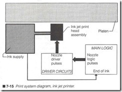
Where impact and thermal printing depend on actual contact be tween the head and paper, ink jet printing provides a “noncontact” printing medium. Noncontact printing is accomplished by spray ing liquid ink onto a page from individual ink nozzles. The block di agram for an ink jet print system is shown in figure 7-15. In many ways, this is the same approach used for serial impact and thermal printers, with the notable exception of a liquid ink supply. De pending on the partic ular print head design, ink might be located in a large reservoir away from the head, or in a small reservoir in tegrated into the print head assembly. Older ink jet print heads usually hold 9, 12, or 24 nozzles, but contemporary print heads can 167
carry 50 nozzles or more. Each nozzle can be frred independently, so the ink jet system is capable of producing high-quality characters and graphics on plain paper .
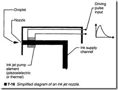
Like other serial print heads, ink jet images are formed one char acter line at a time while the print head sweeps back and forth across the page. Characters that are received from a host com puter are converted into a series of vertical dot patterns recalled from the printer’s permanent memory. Each dot pattern is sent in turn to the head as it moves. Driver circuits amplify and condition signals produced by main logic into the short, high-energy pulses that are needed to operate each ink nozzle. As a pulse reaches an ink nozzle, it causes a small piezoelectric ring or heating element around the nozzle to constrict. This sudden constriction literally launches a droplet, as shown in figure 7-16.
Cleaning ink jet heads
The proper operation of an ink jet head depends largely on the vis cosity of the ink, and its surface tension at each nozzle. During normal use, it is perfectly natural for ink to evaporate. Unfortu nately, this raises the ink’s viscosity and its surface tension, which ultimately clogs the nozzles. The other enemy of ink nozzles is for eign matter, ink mixed with everyday dust and dirt, which can work into nozzles and also cause clogs. Virtually all contemporary ink jet printer designs incorporate some type of “ink cap” that will seal off the nozzles while the printer is idle. Such caps often take the form of small sponges. As printers age, however, the ink sponges dry out and lose their pliability, so older printers tend to have more serious clogging problems than newly built printers. In actual practice, you will probably encounter clogging problems with most ink jet printers from time to time. Fortunately, they are easy devices to clean.
Some printers are equipped with a PURGE (sometimes called PRIME) function, which is especially intended to clear clogs auto matically. You need only press the PRIME button, then recheck the printer. If the problem persists, you should try cleaning the nozzles with a soft cloth or cotton swab dampened lightly in iso propyl alcohol. Note that you will need to turn off and unplug the printer, then remove the print head cartridge for this operation. Wipe the nozzles gently, and make sure that the cartridge face is dry before reinstalling. If the clog still won’t clear, check the ink cartridge for a manual PRIME port, which can usually be actuated manually with a paper clip. Be sure to rest the print cartridge on a clean, highly absorbent material; purging will push ink out of the cartridge, which can easily cause a mess. When you press on the PRIME port, press gently; you do not want to rupture the ink blad der. Ifneither cleaning nor purging will clear the clog, you will sim ply have to replace the ink jet print head.
Refilling ink jet print heads
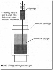
If you deal with a large number of ink jet cartridges and you find yourself throwing a large number of them away, you might con sider recycling (refilling) the exhausted ink cartridges yourself. You can refill a cartridge with bulk ink, a syringe, and a small drill (#55 or so). The refill process typically involves using the drill to create or enlarge a hole in the ink cartridge (such as shown in fig ure 7-17). Draw some ink into the syringe (12 to 15 cc), push the syringe into the ink head as far is it will go, then inject ink slowly and lift up slightly as you go to distribute the ink. The process takes several minutes, and costs a fraction of a new ink cartridge. If you do choose to refill ink cartridges as a sideline, you can fmd an excellent reference in The Ink Jet Cartridge Book, published by The Tech Press.
Limited cartridge life
Another important attribute to keep in mind when working with ink jet cartridges is their limited life. Ink does not remain viable in definitely; the unavoidable evaporation of solvent in the ink will eventually clog the print head, or reduce the cartridge’s life. There are two expiration dates to keep in mind when selecting and purchasing ink cartridges: the sealed (or “shelf’) life and the printer life. New ink cartridges are typically marked with a “use by” date. The diff erence between the current date and the use by date is the shelf life. Ifyou intend to stock a quantity of ink cartridges, be sure to purchase fresh uni ts. A typical shelf life is 18 months from the date of manufacture . Once an ink cartridge is opened and installed in a printer, the ink has a printer life (usually no more than three months from the date it is opened). Of course, regular use will probably exhaust the ink cartridge before the three months has expired. The major idea to remember here is that ink will become unusable in a matter of months.
Evaluating the print head
The first step in all diagnosis is examinati on. In the case of ink j et print head testing, you should print a sample page that will place the print head und er a certain amount of stress. You can discern glaring problems while printing ordinary text, but to really push the print head’s capabilities, the prin ter shouJd generate a de-
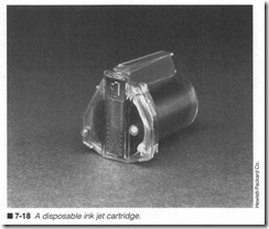
prime, and retest the print head. Replenish your ink supply or re place the entire ink cartlidge if necessary. Replaceable ink jet car tridges, as shown in figure 7-18, can often be cleaned and primed easily. Use a clean cotton swab dipped lightly (if necessary) in ethyl alcohol to wipe the face of each nozzle. When nozzles are clean, use the stick to push gently on the ink bladder. This forcesfresh ink through the head (be sure to wipe up any spillage before reinstalling the ink cartridge) . The head should now be ready to retest.
manding graphic. You can use the companion utility PRINTERS to generate a print head test pattern, such as a test page or the large black rectangle shown in figure 7-5. By observing inconsistencies in the resulting image, you can make an accurate determination of the print problems. Of course, if you have other utilities that will generate similar results, feel free to use them as well.
Troubleshooting the ink jet heads
Contemporary ink jet print heads are a mixed blessing for techni cians. Their simple, modular design and internal ink supply make them a snap to replace; the overall process requires no more than 10 seconds. The ink cartridge is also reasonably reliable because there are essentially no moving parts. However, the proliferation of microscopic nozzles in today’s ink jet heads are almost impossi ble to keep clean over the long term (and clogged nozzles are readily noticeable). Even when a nozzle does not clog completely, an accumulation of foreign matter can deflect the droplets and cause splattering, ruining the fine detail in high-resolution graph ics. When an ink jet print head problem does occur, the entire head will have to be replaced.
Symptoms
Symptom 1 Print quality is poor. Print appears smeared, faint, or smudged. Print quality problems are often related to the charac teristics of the paper being used. Ideally, liquid ink should dry im mediately as it sticks to the paper, resulting in a neat, crisp appearance that will not smudge when touched. Just how quickly the ink actually dries depends on the characteristics of the ink, as well as the paper. Paper that absorbs ink readily might drink up too much ink from the page surface. This can result in a faded or dull appearance. On the other hand, glossy paper or paper that does not ink well might allow ink to smudge or smear through rollers or when touched. Typical ink jet printer paper is impreg nated with clay or chemicals that will absorb ink quickly on con tact, but not so fast that it disappears into the paper. You can usually identify “ink jet” paper by its shiny, smooth appearance on one side, and its normal, dull appearance on the other side.
Inspect your ink supply and ink nozzles carefully. In most contem porary ink jet designs, the ink supply is manufactured into a dis posable cartridge along with the ink nozzles. A low ink supply or partially clogged nozzle can cause some nozzles to spit or sputter, resulting in a smudged appearance. Follow procedures to clean,
Finally, check yow· print head spacing. If your print head is too close, ink impacting the page might spatter or run. A head that is too far away might produce print that appears to sag acro s a printed line. Most printers allow head spacing to be adjusted by several thousandths of an inch using a mechanical lever assembly, such as in figure 7-6. Your user’s manual probably lists the opti mum distance settings for various paper thicknesses.
Symptom 2 Print contains one or more missing lines. This also hap pens when ptinting self-tests or test pages. Refer to Chart 7-5. Be gin by checking your ink supply. If the supply is marginally low, there might not be enough ink to supply every nozzle evenly. Noz-
zles that do not receive ink will not fire, even if they are working properly. Replaceable ink cartridges with local ink reservoirs are usually easy to check. If the ink bladder appears low, simply re place the cartridge. Nonreplaceable ink jet heads might be a bit more difficult to check, but you should replenish the reservoir if it appears low. You might also want to replace any ink jet cartridges that have expired, or that have been in the printer longer than three months.
If the ink level is satisfactory, one or more ink nozzles might be ob structed with foreign matter or clogged with dried ink. Clean, prime, and retest the print head. Use a cotton swab dipped lightly in ethyl alcohol to wipe off each nozzle, then use its wooden end to gently press on its ink bladder. This forces fresh ink through the head. Make sure that fresh ink beads up on every nozzle. It should now be ready to retest. If cleaning does not help, try a new ink jet cartridge.Missing lines can be caused by a fault in the print head cable. In termittent or broken signal lines can disable any of the nozzles. Unplug the printer and use your multimeter to check continuity across each conductor in the print head cable. You might have to disconnect the print head cable at one end to prevent false conti nuity readings. Replace the print head cable if you find it to be ex cessively worn or defective.
If a new ink cartridge does not resolve the problem and everything else checks properly up to this point, the trouble is probably in your driver circuits, or inthe main logic of the ECU. If you have an oscilloscope available, you can check the input and output signals of the drivers that correspond to the suspected nozzles. If a logic input signal is present but a high-power signal is not, the driver stage is bad and should be replaced. If the logic input signal is missing, the logic of the ECU is probably at fault and should be re placed. Of course, if an oscilloscope is not handy, you should re place the driver circuits first. If that does not correct the problem, replace the main logic portion of the ECU. In printers where the main logic and driver circuits are combined onto the same board, you should replace the entire ECU outright.
Symptom 3 Print contains one or more black lines. This also hap pens during a self-test or test page. Check your print head cable first. There might be a short circuit between two or more nozzle signals. Turn off and unplug the printer, then use your multimeter to check continuity between individual cable wires. You should disconnect the cable from at least one end to prevent false continuity readings. Ideally, all print signal wires should be isolated from one another (infinite resistance). Replace the print head ca ble or connectors if they appear shorted.
If problems persist, the fault might be in your ink jet print head. Try a new ink jet cartridge. If that fails to correct the problem, you can be confident that the trouble is located in the driver circuits or main logic. Try replacing the driver assembly first. If problems con tinue, replace the main logic board. In printers where the driver circuits and main logic are integrated onto the same board, you should just replace the entire ECU outright.
Symptom 4 Printer does not print under computer control. Opera tion appears correct in its self-test mode. Make sure that your printer is actually on-line with the host computer. An indicator will usually be lit on the control panel when your printer is selected (on-line). If your printer is off-line for any reason, it can not com municate with the computer, even if everything is working prop erly. A printer can be off-line for several reasons. Paper might be exhausted. This inhibits operation until paper is replenished and reselected manually. In order to access any of the functions avail able from a printer’s control panel (e.g., font style, character pitch, line width, etc.), the printer must go off-line, then be reselected after its modes have been changed. If functions are selected incor rectly, or you forget to reselect the printer, it will not operate un der computer control. Finally, make sure that your computer software is configured properly for your particular printer. You might have to select a new printer driver.
The communication interface cable might have become loose or detached at one end. If it is a new or untested cable, make sure that it is wired correctly for your particular equipment interface. Cables that are prone to flexing or bending might have developed a faulty connection. Disconnect the cable at both ends and use your multimeter to measure continuity through the cable. Repair or replace any defective communication cable.
Examine your DIP switch settings next. DIP switches are used to change optional settings, such as serial communication format, character sets, or automatic line feed. If this is a new installation, or you have just set up the printer for a different computer, there might be an error in these settings. DIP switches also tend to be come unreliable after many switch cycles. If you suspect a faulty switch, rock it on and off several times, then retest the printer. If problems continue at this point, there is probably a fault in the ECU’s communication circuitry. You might troubleshoot or replace the ECU at your discretion as discussed in Chapter 9.
Symptom 5 Print is intermittent or absent. All other functions ap pear correct. Intermittent or missing print can be the result of a low ink supply or trouble with the ink flow, so inspect your nozzles and ink flow carefully. A low ink supply might not be able to provide ad equate ink to all nozzles at all times, especially while printing dark graphics. You might see this as randomly occurring areas of missing dots. In severe conditions, print might disappear entirely. A clog or restriction in the ink supply can also limit ink that is available at the nozzles. If the head has been unused for a prolonged period of time, the nozzles might be clogged with dry ink. Replace your ink car tridge or replenish the ink supply as necessary.
Replaceable ink jet cartridges, as in figure 7-18, can usually be cleaned and primed easily. Use a clean swab dipped lightly in ethyl alcohol to wipe the face of each nozzle, then use the swab’s wooden end to push gently on the ink bladder. This forces fresh ink through each nozzle. When you see ink bead up on every nozzle, the print head is ready for use. Be sure to wipe away any residual ink from the cartridge’s face before reinstalling it in the printer.
A faulty print head cable can cause intermittent or missing print.
Unplug the printer and use your multimeter to check continuity across each print head signal wire. You might have to disconnect the cable from at least one end to prevent any false readings. Wiggle the cable to stimulate any possible intermittent connections. Replace any defective print head cable.
When problems persist, there is likely to be an intermittent fault in the printer’s driver circuits or main logic. Unfortunately, trouble shooting intermittent systems can be an extremely time-consuming and frustrating exercise, so it is often preferable to simply replace the suspect subassemblies. Start by replacing the ink jet driver cir cuit board first, then replace the main logic board. For printers that integrate the drivers and main logic onto the same board, simply re place the entire ECU.
