Autotransformer starters reduce the amount of in-rush current by reducing the voltage applied to the motor during the starting period. Many autotransformer starters contain taps that can be set for 50%, 65%, or 80% of the line voltage. Reducing the voltage applied to the motor not only reduces the amount of in-rush current, but also reduces the motor torque. If 50% of the normal voltage is connected to the motor, the in- rush current will drop to 50% also. This will produce a torque that is 25% of the value when full voltage is connected to the motor. If the motor torque is in- sufficient to start the load when the 50% tap is used, the 65% or 80% taps are available.
Autotransformer starters are generally employed to start squirrel cage type motors. Wound rotor type motors and synchronous motors do not generally use this type of starter. Autotransformer starters are inductive type loads and will affect the power factor during the starting period.
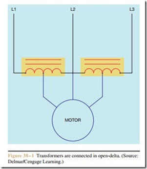
Most autotransformer starters use two transformers connected in open-delta to reduce the voltage applied to the motor during the period of acceleration (Figure 38 – 1). During the starting period, the motor is connected to the reduced voltage taps on the trans- formers. After the motor has accelerated to about 75% of normal speed, the motor is connected to full
voltage. A time delay starter of this type is shown in Figure 38 – 2. To understand the operation of the auto- transformer starter more clearly, refer to the schematic diagram shown in Figure 38 – 2. When the Start button is pressed, a circuit is completed to the coil of control relay CR, causing all CR contacts to close. One contact is employed to hold CR coil in the circuit when the Start button is released. Another completes a circuit to the coil of TR timer, which permits the timing sequence to begin. The CR contact connected in series with the normally closed TR contact supplies power to the coil of S (start) contactor. The fourth CR contact permits power to be connected to R (run) contactor when the normally open timed TR contact closes.
When the coil of S contactor energizes, all S contacts change position. The normally closed S contact connected in series with R coil opens to prevent both S and R contactors from ever being energized at the same time. This is the same interlocking method used with reversing starters. When the S load contacts close, the motor is connected to the power line through the autotransformers. The autotransformers supply 65% of the line voltage to the motor. This reduced voltage produces less in-rush current during starting and also reduces the starting torque of the motor.
When the time sequence for TR timer is completed, both TR contacts change position. The normally closed TR contact opens and disconnects contactor S from the line, causing all S contacts to return to their normal position. The normally open TR contact closes and supplies power through the now closed S contact to coil R. When contactor R energizes, all R contacts change position. The normally closed R con- tact connected in series with S coil opens to provide interlocking for the circuit. The R load contacts close and connect the motor to full voltage.
When the Stop button is pressed, control relay CR de-energizes and opens all CR contacts. This disconnects all other control components from the power line, and the circuit returns to its normal position. A wiring diagram for this circuit is shown in Figure 38 – 3.
