Direct-Current Motors
A direct-current motor is a machine for converting de electrical energy into rotating mechanical energy. The principle underlying operation of a de motor is called motor actions, based on the fact that when a wire carry ing current is placed in a magnetic field, a force is exerted on the wire, moving it through the magnetic field. There are three elements of motor action as it takes place in a de motor:
1. Many coils of wire are wound on a cylindrical rotor or armature on the shaft of the motor.
2. A magnetic field necessary for motor action is created by plac ing fixed electromagnetic poles around the inside of the cylindrical motor housing. When current is passed through the fixed coils, a magnetic field is set up within the housing. Then, when the arma ture is placed inside the motor housing, the wires of the armature coils will be situated in the field of magnetic lines of force set up by the electromagnetic poles arranged around the stator. The station ary cylindrical of the motor is called the stator.
3. The shaft of the armature is free to rotate because it is sup ported at both ends by bearing brackets. Freedom of rotation is assured by providing clearance between the rotor and the faces of the magnetic poles.
DC MOTOR CONSTRUCTION
The frame (Fig. 8-1) is made of iron to be used to complete the magnetic circuit for the field poles. Traditionally, frames have been made in three types: open, semienclosed, and closed types. The open frame has the end plates or bells open so the air can freely circulate through the machine. The semienclosed frame has a wire netting or small holes in the end bells so that air can enter but will prevent any foreign material entering the machine. The enclosed-type frame has the end bells completely closed, and the machine is airtight. The closed-type frame is used in certain areas such as those classified as hazardous- containing flammable fumes, dust, etc. Some motors are waterproof, enabling them to operate under water.
The field poles (Fig. 8-1) are made from iron, either in solid form or built of thin strips called laminations. The iron field poles support the field windings and complete the magnetic circuit between the frame and armature core.
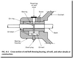
Bearings used in de motors fit around the armature shaft and sup port the weight of the armature as shown in Fig. 8-2. They are made in three general types: sleeve, roller, and ball bearings.
Oil rings, also shown in Fig. 8-2, are small rings used with sleeve type bearings. They carry the oil from the oil well to the shaft. The oil ring must turn when the machine is operating, or otherwise the bearing will burn out.
The rocker arm supports the brush holders. This arm is usually ad justable to make it possible to shift the brushes to obtain best operation. When the brushes are rigidly fastened to the end bell, the entire end-bell assembly is shifted to obtain the best possible operation. See Fig. 8-3.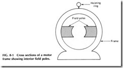
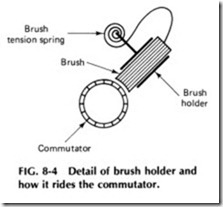
The brush holders support the brushes and hold them in the proper position on the commutator. The brushes should be spaced equidistantly on the commutator when more than two sets of brushes are used. When only two sets are used, they will be spaced the same distance as a pair of adjacent field poles.
The brush tension spring applies enough pressure on the brush to make a good electrical connection between the commutator and brush. See Fig. 8-4.
Brushes used on de motors are made of copper, graphite, carbon, or a mixture of these materials. The purpose of the brushes is to complete the electrical connection between the line circuit and the armature winding.
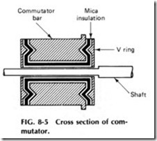
Commutators (Fig. 8-5) are constructed by placing copper bars or segments in a cylindrical form around the shaft. The copper bars are insu lated from each other and from the shaft by mica insulation. An insulat ing compound is used instead of mica on small commutators. The com mutator bars are soldered to and complete the connection between the armature coils.
The armature core (shown in Fig. 8-6) is made of laminated iron pressed tightly together. The laminated construction is used to prevent induced currents (eddy currents) from circulating in the iron core when the machine is in operation. The iron armature core is also a part of the magnetic circuit for the field and has a number of slots around its entire surface in which the armature coils are wound.
The armature winding (Fig. 8-7) is a series of coils wound in the armature slots, and the ends of the coils connect to the commutator bars. The number of turns and the size of wire are determined by the size, speed, and operating voltage of the machine. The purpose of the armature winding is to set up magnetic poles on the surface of the armature core.
The field windings are made in three different types: shunt-, series-, and compound-wound fields. Shunt fields have many turns of small wire, and series fields have a few turns of heavy wire. The compound field is a combination of the two windings. The name of the field winding depends on the connection with respect to the armature winding, and its purpose is to produce magnetic poles that react with the armature poles to pro duce rotation.
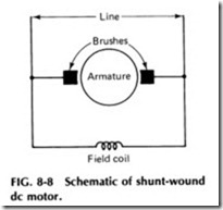
SHUNT-WOUND DC MOTORS. In this type of motor (Fig. 8-8), the strength of the field is not affected appreciably by change in the load, so that a relatively constant speed is obtainable. This type of motor may be used for the operation of machines requiring an approximate constant speed and imposing low starting torque and light overload on the motor.
The shunt-wound de motor can be made into an adjustable-speed motor by means of field control or by armature control. For example, if a variable resistance is placed in the field circuit, the amount of current in the field windings along with the speed of rotation can be controlled. As the speed increases, the torque decreases proportionately, resulting in nearly constant horsepower. A speed range of 6 to 1is possible using field control, but a lesser ratio is more common.
Speed regulation is somewhat greater than in the constant-speed shunt-wound motors, ranging from about 15 to 22o/o. If a variable resistance is placed in the armature circuit, the voltage applied to the arma ture can be reduced, in turn reducing the speed of rotation over a range of about 2 to 1. With the armature control, speed regulation becomes poorer as speed is decreased and is about 100o/o for a 2 to 1 range. The torque of this type of motor remains constant because the current through the field remains unchanged during operation.
Adjustable-speed shunt-wound motors are very useful on larger ma chines of the boring mill, lathe, and planer type and are particularly adapted to spindle drives because constant-horsepower characteristics permit heavy cuts at low speed and light or finishing cuts at high speed. They have long been used for planer drives because they can provide an adjustable low speed for the cutting stroke and a high speed for the return stroke. Their application has been limited, however, to plants where de power is available, nowadays requiring the plant itself to either generate de power or convert ac to de.
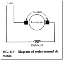
SERIES-WOUND DC MOTORS. In motors of this type (Fig. 8-9), any increase in load results in more current passing through the armature and the field windings. As the field is strengthened by this increased cur rent, the motor speed decreases. Conversely, as the load is decreased, the field is weakened, and the speed increases, and at very light loads speed may become excessive. For this reason, series-wound motors are usually
directly connected or geared to the load to prevent runaway. The increase in armature current with an increasing load produces increased torque, so that the series-wound motor is particularly suited to heavy starting duty and where severe overloads may be expected. Its speed may be adjusted by means of a variable resistance placed in series with the motor, but due to variation with load, the speed cannot be held at any constant value. This variation of speed with load becomes greater as the speed is reduced. Use of this motor is normally limited to traction and lifting service.
COMPOUND-WOUND MOTORS. In this type of motor (Fig. 8-10), the speed variation-due to load changes-is much less than in the series-wound motor but greater than in the shunt-wound motor. It also has a greater starting torque than the shunt-wound motor and is able to withstand heavier overloads. However, it has a narrower adjustable speed range. Standard motors of this type have a cumulative-compound winding, the differential-compound winding being limited to special ap plications. They are used where the starting load is very heavy or where the load changes suddenly and violently as with reciprocating pumps, printing presses, and punch presses.
Compound-wound motors use both shunt (parallel) and series field coils and have characteristics between both. In general, there are four dif ferent kinds of compound motors:
1. Long-shunt cumulative
2. Long-shunt differential
3. Short-shunt cumulative
4. Short-shunt differential
LONG-SHUNT CUMULATIVE. In this type of motor, the cur rent flows through the series field and shunt field coils of a pole in the same direction as shown in Fig. 8-11. When the shunt field is connected across the line, it is given the name of long shunt.
LONG-SHUNT DIFFERENTIAL. If the shunt field connection of a compound motor is reversed with respect to the series field, the cur rent will flow through it in the opposite direction as shown in Fig. 8-12. This produces bucking fields, and the motor is known as a differentially connected motor. Therefore, a motor with its shunt field connected across the line so that the series and the shunt fields have opposite polarity in the same pole is known as the long-shunt differential motor.
SHORT-SHUNT CUMULATIVE. When the shunt field of a com pound motor is connected to the armature terminals instead of across the line, the motor is known as a short-shunt motor. When the shunt is con nected across the armature so that the current flows through it in the same direction as in the series field, the motor is known as a short-shunt cumulative motor.
SHORT-SHUNT DIFFERENTIAL. If connected so that the cur rent flows through the shunt field in the opposite direction to the current in the series field, the motor is known as a short-shunt differential motor as shown in Fig. 8-13.
Compound motors, like series motors, are known as variable-speed motors because the speed varies with the load. Therefore, the compound motor is normally used for two types of work: loads requiring relatively constant speed but having frequent peaks needing high torque such as compressors and reciprocating pumps and on applications requiring the motor to sometimes run without load, such as winches, hoists, and the like.
High starting current must be reduced by adding external resis tance to the motor; the speed is regulated by changing the armature resistance, the field strength, or the applied voltage. Motor ratings de pend on temperature limitations during operation, and manufacturers provide guarantees for allowable speed regulation of different types of motors.
BRUSH LESS DC MOTORS
The brushless de motor was developed to eliminate commutator prob lems in missiles and spacecraft in operation above the earth’s atmo sphere. Two general types of brushless motors are in use: the inverter induction motor and a de motor with an electronic commutator.
The inverter-induction motor uses an inverter which uses the motor windings as the usual filter. The operation is square wave, and the combined efficiencies of the inverter and induction motor are at least as high as for a de motor alone. In all cases, the motors must be designed for lowstarting current, or else the inverter must be designed to saturate so that starting current is limited; otherwise the transistors or silicon-controlled rectifiers in the inverter will be overloaded .
MOTOR BRAKING
Motor brakes are composed of a linkage of moving parts and a friction member. Different types of brakes are available depending on the power supply, ratings, and the application requirements.
The torque ratings of the brake is usually selected at least equal to the full-load torque of the motor. There are cases in which this value should be exceeded, where it is necessary to stop the machine very quick ly or to provide an adequate margin of safety.
The time rating of brakes is controlled by the amount of heating pro duced in the brake coil or thrustor motor. The brake time rating is usually made at least equal to the motor time rating, since the brake is energized as long as the motor is energized.
Continuous rated brakes are applied where conditions of inter mittent-duty rating cannot be met. Also continuous rated brakes should be applied when any doubt exists that the intermittent-duty rating will be exceeded.
Intermittent-duty shunt-wound de brakes should not be energized for more than one half of the off-on cycle with continuous application of normal voltage not exceeding 1 h. The same intermittent-duty time ap plies for ac brake coils and thrustor brakes with the exception that they shall not release more than three times per minute.
Since de series brake coils are applied only with series-wound motors-which are usually applied either on a V2- or 1-h basis-the brake coil time rating is again made at least equal to the motor time rating. Disc brakes are usually applied on the basis of continuous duty.
Types SA and SAR self-adjusting de magnetic brakes can be used for fast stopping of any de motored drive. They are self-adjusting, require minimum maintenance, and are supplied with either shunt or series coils.
Direct-current-type SAR Rectox operated brakes are employed where the smooth operation of a de brake is desired on an ac motor. The SAR brake uses a standard shunt coil plus an interlock. This brake is cap able of applying the intermittent torque rating continuously due to the interlock feature.
DYNAMIC BRAKING
Dynamic braking can be used with synchronous and induction motors. On de shunt and compound motors, the armature is disconnected from the line and quickly connected to a resistor. The shunt field remains ener gized. The generator or braking action decreases with the speed and stops the motor quickly. Most machines, especially machine tools, have considerable friction, and dynamic braking provides extremely rapid and uniform results with no mechanical wear or maintenance. However, a ma chine with little friction would drift at lower speeds. Also, with such a machine, an overhaulting load might not stop with the motor.
On adjustable-speed motors, a relay is provided which short-circuits the field theostat during braking, giving maximum field strength and materially decreasing the time of travel during braking. Schematic braking connections for shunt motors, of either constant or adjustable speed, are shown in Fig. 8-13.
Dynamic braking is used on synchronous motors for quick stopping when a safety bar is operated in the case of emergency. The de field is left energized, and the motor is disconnected from the ac line and connected to a three-phase resistor. By using quick-acting control sequences and the proper resistors, any size motor can be stopped in approximately 1s without undue shock or stresses.
Dynamic braking of induction motors is comparatively new, but it is growing rapidly in applications for many textile and machine tool drives.
When the starter is opened, de voltage is applied to two or more stator terminals. Suitable interlocking of contactors is required so that the starter and de contactor cannot be closed at the same time; also, a timing relay is required to open the braking contactor after the motor has stopped. The resistance of ac motor windings is low, so that if a 125-V de supply is used, external resistors are generally required to limit the braking current. As a rule, satisfactory braking is obtained with a current from two to three times the full-load rated amperes of the motor.
With dynamic braking, there is no tendency to reverse the motor, and where safety to operators is involved, this feature is often of major importance.
