CALCULATORS
The pocket calculator is a very complicated digital system. It is revealing to take apart a modern miniature calculator.In a calculator there is a battery, the tiny readout displays, a few wires from the keyboard, and a printed circuit board with an IC attached. That single IC is most of the digital
system we call a calculator and contains an LSI chip that performs the task of thousands of logic gates. The single IC performs the storage, processing and control functions of the calculating system. The keyboard is the input and the displays are the output of the calculator system.
STRUCTURE OF A CALCULATOR
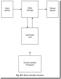
A calculator is really a special purpose computer containing a number of fixed program routines which may be initiated by entering such commands as +, –, ×,÷. Numerical data are entered for the programs to operate on. Since the calculator is essentially a special kind of computer, it has a similar internal structure. This structure is illustrated in Fig. 46.1.
Input Devices : The most common, input device to a calculator is keyboard. This is merely a group of keyswitches, each representing a digit or an operation, which will be understood by the calculator when a key is depressed. Each key, when depressed, causes a binary code to be generated and passed to the processing section of the calculator. There is a unique code for each key so that the processor can decode it and know how to handle the information.
A more complex calculator may have other input devices such as magnetic or punched cards or tapes. However, they all operate on the same principle, that of providing unique codes to identify the various digits and operations.
Data Storage : When data is entered into the calculator it must be stored so that it can later be operated upon by the processor or arithmetic unit. There are various ways in which the store may be arranged. Basically, the arrangement may be such that groups of digits may be conveniently accessed by the other processing units, each group representing either numbers to be operated upon or the results of an operation. The data storage area is generally made up of register stages.
A register is a memory circuit used for remembering multidigit numbers. Mostly four-function calculators have atleast three operating registers that are used in entering the numbers to be used, displaying them and carrying out the arithmetic operations. More sophisticated scientific calculators have more registers.
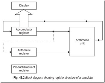
Figure 46.2 shows the basic register arrangement used in most of our function calculators. The most important register is called the keyboard or display register. It is also referred to as the accumulator register. When you enter data via the keyboard the numbers are stored in this register and the display is connected to this register so you will see the numbers as they are entered. When you depress a function key and then begin entering the next number to be used in the calculation the first number is transferred out of the accumulator into another register which we can call the arithmetic register. After the second number is entered the equals key is usually depressed to initiate the computation, and the numbers stored in these two registers are then sent to the arithmetic unit which is an adder/subtractor. The sum or difference, answer is stored back in the accumulator, and is displayed. The number stored there previous to the calculation is lost; the number in the arithmetic register is retained but we usually cannot get to it. Only these two registers are used in addition and subtraction.
![]() The third register is used when multiplication and division operations are perfomed. These functions are performed by successive additions and subtractions. Since the product or quotient numbers can be twice as long as the numbers you start, with additional memory space is required. The product/quotient register provides this extra storage.
The third register is used when multiplication and division operations are perfomed. These functions are performed by successive additions and subtractions. Since the product or quotient numbers can be twice as long as the numbers you start, with additional memory space is required. The product/quotient register provides this extra storage.
The registers used in modern electronic calculators are called shift registers since during data entry, transfer and calculation, the numbers are shifted into and out of the registers, a digit at a time. The registers in a caculator are often referred to as the stack register or the random access memory (RAM).
The Arithmetic Unit : The arithmetic unit, as its name implies, performs arithmetic operations on the data in the storage registers. It consists of an adder circuit, or an adder/subtractor, typically resembling the serial or parallel adders. A single-bit storage register is usually included so that the carry condition from a previous operation may be remembered.
Data is passed to the arithmetic unit from the storage registers and is there operated upon, the result being passed back to the appropriate register. This section of calculator is also used to detect the codes which have been input from the keyboard. By adding numerical constants to the codes and detecting the presence or absence of a carry generated, the code may be identified and the appropriate action taken. It is necessary, for example, to distinguish whether a keyboard input is a digit or an operator.
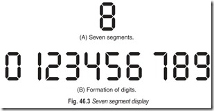
Ouput Devices : The most common output devices used with calculators are printers or luminous displays. A printer has the obvious advantage of giving a permanent record of the data, this being typically a strip of paper containing ten to fifteen digits per line of print. Luminous displays, Fig. 46.3, have the advantages of lower power consumption, so important for small calculators and fast response time. Data from the storage registers is output to the display device under control of the calculator. The binary codes representing the numbers have to be decoded by suitable logic circuits so that the required digit is displayed after it has been read out from the store.
The Control Section : The control section contains the programs which govern the operations to be performed on data in order to produce the answer to the required problem. The program consists of many binary coded instructions held in a read only memory (ROM). The instructions are read from this program memory sequentially and decoded to perform the required control functions. Such control functions include selecting the appropriate register data and routing it to the adder, sending data back to the register, outputting data to the display, selecting an add or subtract mode for the adder, examining the carry bit and many more. The instructions are executed sequentially by means of a program counter which selects one instruction after another from the program memory. The apparently simple problem of adding together two numbers would typically require a few hundred program steps to be executed. We can see how fast the individual operations are performed since the answer is calculated in a fraction of a second.
INTERNAL ORGANISATION OF A CALCULATOR
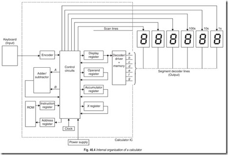
The diagram in Fig. 46.4 will help us figure out how a calculator works. Figure 46.4 shows three components
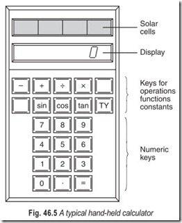
: the keyboard, the seven-segment displays and the power supply. These parts are the only functional ones not contained in the single LSI IC in most calculators. The keyboard is obviously the input device. The keyboard contains simple normally open switches. The decimal display is the output. The readout unit in Fig. 46.4 contains only six seven-segment displays. The power supply is a battery supply in most inexpensive hand-held calculators. Many modern caculators use solar cells as their power supply. CMOS ICs and LCD make this supply feasible.
The calculator chip (the IC) is divided into several functional subsystems as shown in Fig. 46.4. The organisation shown is only one of several ways to get a calculator to operate. The heart of the system is the adder/subtractor subsystem. The clock subsystem pulses all parts of the system at a constant frequency. The clock frequency is fairly high ranging from 25 to 500 kHz. When the calculator is turned on, the clock runs constantly and the circuit is idle until a command comes from the keyboard.
Suppose we add 2 + 3 with this calculator. As we press the 2 on the keyboard, the encoder translates 2 to a BCD 0010. The 0010 is directed to the display register by the control circuitry and is stored in the display register. This information is also applied to the seven-segment decoder and lines a, b, d, e, and g are activated. The first (Is display) seven-segment display shows a 2 when the scan line pulses that unit briefly. The scanning continues at a high-frequency, and the display appears to be lit continuously even though it is being turned on and off many times per second. Next, we press + on the keyboard.This operation is transferred to and stored in code form in an extra register (X register). Now we press 3 on the keyboard. The encoder translates the 3 to a BCD 0011. The 0011 is transferred to the display register by the controller and is passed to the display decoder/driver which also places a 3 on the display. Meanwhile, the controller has moved the 0010 (decimal 2) to the operand register. Now we press = key. The controller checks the X register to see what to do. The X register says to add the BCD numbers in the operand and display registers. The controller applies the contents of the display and operand registers to the adder inputs. The results of the addition gets collected in the accumulator register. The result of the addition is a BCD 0101. The controller routes the answer to the display register, shown in the readout as 5.
For longer and more complex numbers containing decimal points, the controller follows directions in the instruction register. For complicated problems the unit may cycle through hundreds of steps as programmed into the ROM. Amazingly, however, even hundreds of operations take less than 1/10s.
Only the original IC designers need to know the organisation of the subsystems in Fig. 46.4. This organisation is sometimes referred to as the architecture of the calculator. Notice that all the elements of a system are present in this electronic calculator.
SERVICING ELECTRONIC CALCULATORS
Small electronic calculators require more sophisticated troubleshooting techniques than those employed in servicing many other kinds of electronic equipment. In addition to the basic procedures used in discrete transistor circuits, calculator servicing requires some understanding of integrated circuitry and logic.
To service a defective calculator you will need a pencil-type soldering iron (30 to 40 watts at about 700°F), small screwdrivers, solder remover, sharp knife, diagonal cutters, and needle-nose pliers. A vom and oscilloscope are the only necessary pieces of test equipment, but a frequency counter can come in handy at times. Some problems can be solved with no test equipment at all or possibly a vom alone.
A few general procedures will save lots of time and reduce the chance of inadvertently damaging additional components in an already defective machine. First, give the machine a careful visual inspection. Burned or bubbly resistors, blown electrolytic capacitors, solder bridges, and other obvious malfunctions can usually be quickly found and corrected. If the problem involves a destroyed component, never install a replacement part until the cause of the problem is found and corrected. Never use a replacement component of less quality than the original one.
Next, although it may be necessary to turn on a calculator to find the symptoms of a problem, never leave a malfunctioning machine on longer than necessary. A good example is the overflow indicator. If the readout devices do not light, multiply two numbers whose product will give an overflow indication. If the “Error” signal is displayed, the problem is not in the input, control, or arithmetic sections of the machine. In this manner, possible causes of the trouble can be quickly identified.
Finally, if a thorough visual inspection fails to reveal the problem, begin troubleshooting at the point of the improper indication and work backward, checking each associated component. If more than one problem exists, begin with the simplest since it frequently leads to the major trouble spot. Here is a typical example :
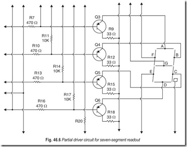
In Fig. 46.6, the C segment in the display fails to light. Follow these steps to isolate the trouble :
1. Check continuity from the C segment to the Q5 emitter
2. Check the Q5 base for proper incoming signal
3. Check Q5
4. Check R15
5. Check R14
EXERCISES
Descriptive Questions
1. Draw the basic calculator structure. Explain.
2. Explain the internal organisation of a calculator.
3. What are the basic operations performed by a calculator?
Fill in the Blanks
1. A keyboard is merely a group of keyswitches each representing a digit or an………………………………….
2. There is a unique………………………………….for each key so that the processor can decode it and know how to handle the information.
3. Most four-function calculators have at least………………………………….operating registers.
4. Multiplication and division are performed by………………………………….additions and subtractions.
5. The numbers are shifted into and out of the register………………………………….at a time.
6. Luminous displays have the advantage of………………………………….power consumption.
7. The keyboard is obviously the………………………………….device.
8. The decimal………………………………….is the output.
9. The clock subsystem………………………………….all parts of the system at a constant frequency.
ANSWERS
Fill in the Blanks |
||
|
1. operation 4. successive 7. input |
2. code 5. one digit 8. display |
3. three 6. lower 9. pulses |
