Why Transformer Rating in kVA ?
As seen, Cu loss of a transformer depends on current and iron loss on voltage. Hence, total transformer loss depends on volt-ampere (VA) and not on phase angle between voltage and current
i.e. it is independent of load power factor. That is why rating of transformers is in kVA and not in kW.
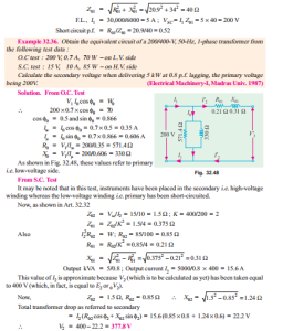
Example 32.35. The primary and secondary windings of a 30 kVA 76000/230, V, 1-phase transformer have resistance of 10 ohm and 0.016 ohm respectively. The reactance of the transformer referred to the primary is 34 ohm. Calculate the primary voltage required to circulate full-load current when the secondary is short-circuited. What is the power factor on short circuit ?
(Elect. Machines AMIE Sec. B 1991)
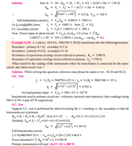
A 1-phase transformer has a turn ratio of 6. The resistance and reactance of primary winding are 0.9 W and 5 W respecitvely and those of the secondary are 0.03 W and 0.13 W respectively. If 330 -V at 50-Hz be applied to the high voltage winding with the low-voltage winding short- circuited, find the current in the low-voltage winding and its power factor. Neglect magnetising current.
Example 32.39. The efficiency of a 1000-kVA, 110/220 V, 50-Hz, single-phase transformer, is 98.5 % at half full-load at 0.8 p.f. leading and 98.8 % at full-load unity p.f. Determine (i) iron loss (ii) full-load copper loss and (iii) maximum efficiency at unity p.f.
(Elect. Engg. AMIETE Sec. A Dec. 1991)
Solution. Output at F.L. unity p.f. = 1000 ´ 1 = 1000 kW
F.L. input = 1000/0.988 = 1012.146 kW
F.L. lossses = 1012.146 – 1000 = 12.146 kW
If F.L. Cu and iron losses are x and y respectively then
x + y = 12.146 kW …(i)
Example 32.41. The low voltage winding of a 300-kVA, 11,000/2500-V, 50-Hz transformer has 190 turns and a resistance of 0.06. The high-voltage winding has 910 turns and a resistance of 1.6 W . When the l.v. winding is short-circuited, the full-load current is obtained with 550-V applied to the h.v. winding. Calculate (i) the equivalent resistance and leakage reactance as referred to h.v. side and (ii) the leakage reactance of each winding.
Solution. Assuming a full-load efficiency of 0.985, the full-load primary current is
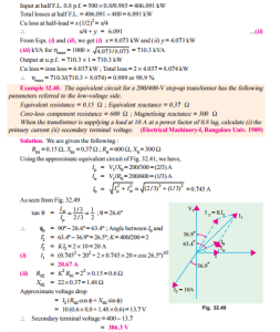
Example 32.42. A 230/115 volts, single phase transformer is supplying a load of 5 Amps, at power factor 0.866 lagging. The no-load current is 0.2 Amps at power factor 0.208 lagging. Calculate the primary current and primary power factor.
(Nagpur University Summer 2000)
Solution. L.V. current of 5 amp is referred to as a 2.5 amp current on the primary (= H.V.) side, at 0.866 lagging p.f. To this, the no load current should be added, as per the phasor diagram in Fig. 32.50. The phase angle of the load-current is 30º lagging. The no load current has a phase angle of 80º lagging. Resultant of these two currents has to be worked out. Along the reference, active components are added.
Active components of currents = 2.5 ´ 0.866 + 0.2 ´ 0.208
Tutorial Problems 32.3
1. The S.C. test on a 1-phase transformer, with the primary winding short-circuited and 30 V applied to the secondary gave a wattmeter reading of 60 W and secondary current of 10 A. If the normal applied primary voltage is 200, the transformation ratio 1 :2 and the full-load secondary current 10 A, calculate the secondary terminal p.d. at full-load current for (a) unity power factor (b) power factor 0.8 lagging.
If any approximations are made, they must be explained.
[394 V, 377.6 V]
2. A single-phase transformer has a turn ratio of 6, the resistances of the primary and secondary windings are 0.9 W and 0.025 W respectively and the leakage reactances of these windings are 5.4 W and 0.15 W respectively. Determine the voltage to be applied to the low-voltage winding to obtain a current of 100 A in the short-circuited high voltage winding. Ignore the magnetising current.
[82 V]
3. Draw the equivalent circuit for a 3000/400-V, I-phase transformer on which the following test results were obtained. Input to high voltage winding when 1.v. winding is open-circuited : 3000 V, 0.5 A, 500 W. Input to 1.v. winding when h.v. winding is short-circuited : 11 V, 100 A, 500 W. Insert the appropriate values of resistance and reactance.
[R0 = 18,000 W, X0 = 6,360 W, R01 = 2.81 W, X01 = 5.51 W] (I.E.E. London)
4. The iron loss in a transformer core at normal flux density was measured at frequencies of 30 and 50 Hz, the results being 30 W and 54 W respectively. Calculate (a) the hysteresis loss and (b) the eddy current loss at 50 Hz.
[44 W, 10 W]
5. An iron core was magnetised by passing an alternating current through a winding on it. The power required for a certain value of maximum flux density was measured at a number of different frequencies. Neglecting the effect of resistance of the winding, the power required per kg of iron was 0.8 W at 25 Hz and 2.04 W at 60 Hz. Estimate the power needed per kg when the iron is subject to the same maximum flux density but the frequency is 100 Hz.
[3.63 W]
6. The ratio of turns of a 1-phase transformer is 8, the resistances of the primary and secondary windings are 0.85 W and 0.012 W respectively and leakage reactances of these windings are 4.8 W and
0.07 W respectively. Determine the voltage to be applied to the primary to obtain a current of 150 A
in the secondary circuit when the secondary terminals are short-circuited. Ignore the magnetising current.
[176.4 W]
7. A transformer has no-load losses of 55 W with a primary voltage of 250 V at 50 Hz and 41 W with a primary voltage of 200 V at 40 Hz. Compute the hysteresis and eddy current losses at a primary voltage of 300 volts at 60 Hz of the above transformer. Neglect small amount of copper loss at no- load.
[43.5 W ; 27 W] (Elect. Machines AMIE Sec. B. (E-3) Summer 1992)
8. A 20 kVA, 2500/250 V, 50 Hz, 1-phase transformer has the following test results :
O.C. Test (1.v. side) : 250 V, 1.4 A, 105 W
S.C. Test (h.v. side) : 104 V, 8 A, 320 W
Compute the parameters of the approximate equivalent circuit referred to the low voltage side and draw the circuit. (R0 = 592.5 W ; X0 = 187.2 W ; R02 = 1.25 W ; X12 = 3 W)
(Elect. Machines A.M.I.E. Sec. B Summer 1990)
9. A 10-kVA, 2000/400-V, single-phase transformer has resistances and leakage reactances as follows :
R1 = 5.2 W, X 1 = 12.5 W, R2 = 0.2 W, X 2 = 0.5 W
Determine the value of secondary terminal voltage when the transformer is operating with rated primary voltage with the secondary current at its rated value with power factor 0.8 lag. The no-load current can be neglected. Draw the phasor diagram.
[376.8 V] (Elect. Machines, A.M.I.E. Sec B, 1989)
10. A 1000-V, 50-Hz supply to a transformer results in 650 W hysteresis loss and 400 W eddy current loss. If both the applied voltage and frequency are doubled, find the new core losses.
[Wh = 1300 W ; We = 1600 W] (Elect. Machine, A.M.I.E. Sec. B, 1993)
11. A 50 kVA, 2200/110 V transformer when tested gave the following results :
O.C. test (L.V. side) : 400 W, 10 A, 110 V.
S.C. test (H.V. side) : 808 W, 20.5 A, 90 V.
Compute all the parameters of the equivalent ckt. referred to the H.V. side and draw the resultant ckt.
(Rajiv Gandhi Technical University, Bhopal 2000) [Shunt branch : R0 = 12.1 k-ohms, Xm = 4.724 k-ohms Series branch : r = 1.923 ohms, x = 4.39 ohms]


Very nice information on transformers are rated in KVA not KW helped me in exam time thank you