Star/Star or Y/Y Connection
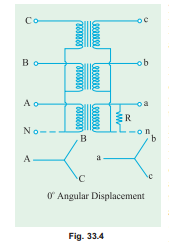
This connection is most economical for small, high-voltage transformers because the number of turns/phase and the amount of insulation required is minimum (as phase voltage is only 1/ 3 of line voltage). In Fig. 33.4 a bank of 3 transformers connected in Y on both the primary and the secondary sides is shown. The ratio of line volt- ages on the primary and secondary sides is the same as the transformation ratio of each transformer. However, there is a phase shift of 30° between the phase voltages and line voltages both on the primary and secondary sides. Of course, line voltages on both sides as well as primary voltages are respectively in phase with each other. This connection works
satisfactorily only if the load is balanced. With the unbalanced load to the neutral, the neutral point shifts thereby making the three line-to-neutral (i.e. phase) voltages unequal. The effect of unbal- anced loads can be illustrated by placing a single load between phase (or coil) a and the neutral on the secondary side. The power to the load has to be supplied by primary phase (or coil) A. This primary coil A cannot supply the required power because it is in series with primaries B and C whose secondaries are open. Under these conditions, the primary coils B and C act as very high impedances so that primary coil A can obtain but very little current through them from the line. Hence, secondary coil a cannot supply any appreciable power. In fact, a very low resistance approaching a short-circuit may be connected between point a and the neutral and only a very small amount of current will flow. This, as said above, is due to the reduction of voltage Ean because of neutral shift. In other words, under short-circuit conditions, the neutral is pulled too much towards coil a. This reduces Ean but increases Ebn and Ecn (however line voltage
practically reduced to zero whereas EBN and ECN will rise to nearly full primary line voltage. This difficulty of shifting (or floating) neutral can be obviated by connecting the primary neutral (shown dotted in the figure) back to the generator so that primary coil A can take its required power from between its line and the neutral. It should be noted that if a single phase load is connected between the lines a and b, there will be a similar but less pronounced neutral shift which results in an overvoltage on one or more transformers.
Another advantage of stabilizing the primary neutral by connecting it to neutral of the generator is that it eliminates distortion in the secondary phase voltages. This is explained as follows. For delivering a sine wave of voltage, it is necessary to have a sine wave of flux in the core, but on account of the characteristics of iron, a sine wave of flux requires a third harmonic component in the exciting current. As the frequency of this component is thrice the frequency of the circuit, at any given instant, it tends to flow either towards or away from the neutral point in all the three transformers. If the primary neutral is isolated, the triple fre- quency current cannot flow. Hence, the flux in the core cannot be a sine wave and so the voltages are distorted. But if the primary neutral is earthed i.e. joined to the generator neutral, then this provides a path for the triple-frequency currents and e.m.fs. and the difficulty is overcome. Another way of avoiding this trouble of oscillating neutral is to provide each of the transformers with a third or tertiary winding of relatively low kVA rating. This tertiary winding is connected in D and provides a circuit in which the triple-frequency component of the magnetising current can flow (with an isolated neutral, it could not). In that case, a sine wave of voltage applied to the primary will result in a sine wave of phase voltage in the secondary. As said above, the advantage of this connection is that insulation is stressed only to the extent of line to neutral voltage i.e. 58% of the line voltage.
Related posts:
Incoming search terms:
- star star connection
- star star transformer connection
- star star transformer
- star/star transformer work satisfactorily when
- application of star star connection
- applications of star star connection
- y y connection using
- star to star connection of transformer
- delta/star transformer works satisfactorily when
- star star transformer applications
- star star connection of power transformer
- star star transformer operates satisfactory when
- how to three phase transformer y y connection
- How to stabilize the neutral floating in star star connection
- star star connection /3 phase
- three phase transformer star star connection
- y y transformer
- star star connection of transformer
- star star connection in the transformer
- एडवांटेज एंड एप्लीकेशन ऑफ स्टार स्टार ट्रांसफार्मर
- star star 3 phase connection
- Star star c
- advantages of star to star connection of a transformer
- star star conn
- star star conne
- star star connected transformer
- star star connection in three phase transformer#spf=1
- star star connected transformers
- advantages of star star transformer connection
- 3 phase transformer star-star connection
- star star connection 3 phase transformer
- star star connection application
- star star connected transformer application
- Delta/Delta transformers work satisfactorily when
- balanced star-star connection
- delta star transformer work on satisfactorily when
- how to star star connected transformer how to newtral shift
- delta delta connection of transformer works satisfactory when
- inverter connectiin
- line voltage & current is same for delta-delta & star-star
- most economic connection of transformer
- only star connections
- oscillating neutral in 3 phase transformer
- can the tertiary winding of star /delta /star be loaded?
- oscillating neutral in transformer
- oscillatory nodal in Yy connection in transformer
- Phase-shifting transformers mail
- series connection in power star-star transformer
- shifting neutral in star connection
- oscillating neutral in a transformer

