Pushbuttons, Switches and Indicators
Pushbutton, switch and indicator units are manufactured in various styles. While they may differ in appearance, they operate basically the same way. They are available in different IP ratings to suit the environment in which they are to be installed. Pushbuttons with ‘built in’ indicator lamps are also available.
All these devices are generally known as control and signalling units. The more commonly used units are 22 mm in diameter. They are manufactured in metal for mounting on metallic doors of control panels. These doors must be earthed. Plastic versions are also available and are generally used to provide double insulated control stations etc.
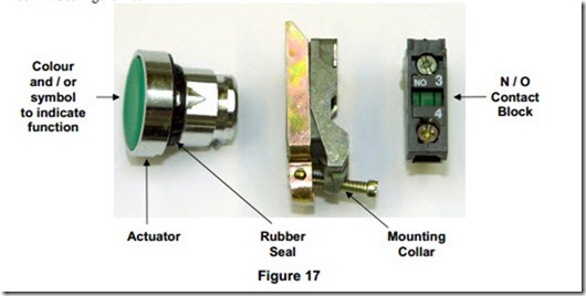
A start button consists of a green coloured actuator, which when pressed operates a normally open contact. On pressing the green actuator the normally open contact will close. These are fitted on the panel door via a mounting collar. The actuator is fitted through a suitable hole in the panel door. A rubber washer is used on the outside to provide ingress protection. The actuator is locked into the collar. The collar is secured to the panel door by a screw. This action compresses the rubber seal on the actuator. Finally the contact block is simply clipped on to the collar. See Figure 17.
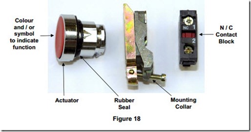
A stop button consists of a red coloured actuator, which when pressed operates a normally closed contact. On pressing the red actuator the normally closed contact will open. See Figure 18
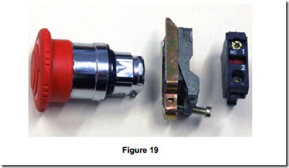
This is an emergency stop button and it differs from a standard stop button as follows:
· It has a large, easy to operate, mushroom shaped actuator.
· This actuator must be mounted on a yellow background.
· When operated, the actuator latches in the “Off “ position.
· The actuator is released by twisting the mushroom shaped head.
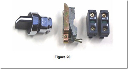
Auto / Off / Hand Selector
This is a three position switch, having an “Off “position in the centre. When turned to the left, a normally open contact is closed. This operation selects an automatic function. When turned to the right, a different normally open contact is closed. This operation selects a manual or hand operated function.
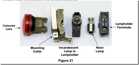
A signal lamp unit consists of an appropriately coloured lens, lamp holder and mounting arrangement similar to a push button unit. A 230 V “small centre contact” ( SCC ) lamp is used in the holder shown in Figure 21. An incandescent lamp or a neon lamp may be used. The phase conductor must be connected to the terminal marked X1.
Other types of signal lamp units are available however they are not covered in Phase 2.
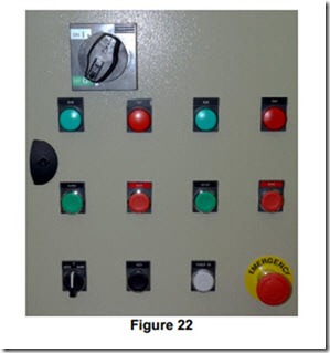
Figure 22 shows a small control panel which consists of a number of the control and signalling devices previously described.
Operation of a Relay
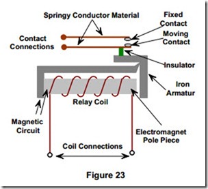
A relay is an electro-magnetically operated switch. It consists of an operating coil wound around an electromagnet pole piece, a moving armature and one or more sets of contacts. When a voltage of the correct value is applied across the coil terminals, the resulting current flow through the coil produces a magnetic field similar to a bar magnet. The armature is attracted by the magnetic field and so moves a small distance.
This movement operates the contact(s). The pole piece is magnetically soft. When current flow through the coil ceases, the pole piece loses its magnetism and the armature returns to its de- energised position. This allows the contact(s) return to the de-energised or normal state.
A relay is a device in which a low value of current and / or voltage operates an electromagnetic coil. This coil in turn operates a contact or contacts, which control or switch a high or relatively high value of current and / or voltage.
Normally Open Contact ( NO )
This is the normal state of the contact when the electromagnet ( coil ) is de-energised. This contact will close instantaneously when the electromagnet is energised. On de-energising the coil, this contact will return to its normal state i.e. open.
Normally Closed Contact ( NC )
This is the normal state of the contact when the electromagnet is de-energised. The contact will open instantaneously when the electromagnet is energised. On de-energising the electromagnet, the contact will return to its normal state i.e. closed.
There are a large number of different designs on the market. In general relays are used to receive an electrical signal from some source ( pushbutton, timeswitch, thermostat, pressure switch ) and relay it on to another device. They are usually capable of switching currents in the region of 10 Amps, although relays up to 30 Amps are available. They are not normally used to switch inductive loads such as electric motors. Some relays are designed for this purpose.
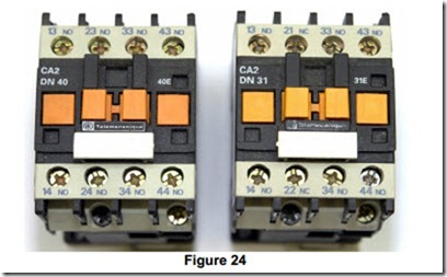
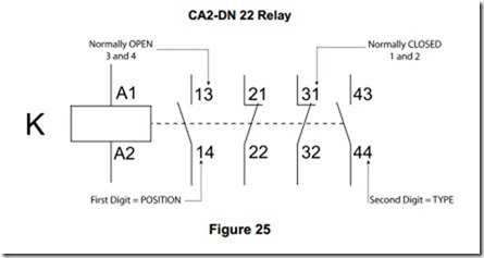
In Phase 2 we examine the type more commonly used in motor control panels. Figure 24 shows two 4 pole ( 4 sets of contacts ) relays. They look identical, but on closer examination they are not. The manufacturer has identified them with type numbers, CA2-DN 40 and CA2-DN 31. The 40 section of the number on the first relay signifies that it has 4 normally open contacts and 0 normally closed contacts. The 31 section of the number on the second relay signifies that it has 3 normally open contacts and 1 normally closed contact.
Each contact is identified by a two digit number. The first digit signifies the position of the contact on the relay 1 to 4 in this case. The second digit signifies the type of contact. A contact marked 1-2 is a normally closed contact. A contact marked 3-4 is a normally open contact. The coil terminals are marked A1 and A2. Relay coils are usually identified by the letter K, followed by a digit up to the total number involved in the circuitry, e.g. K1 to K5.
Note: It is conventional to draw contacts in their de-energised positions.

