An Open Reel Digital Recorder
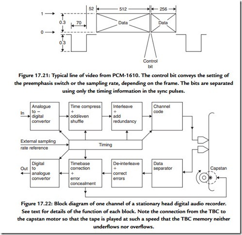
Figure 17.22 shows the block diagram of a machine of this type. Analogue inputs are converted to the digital domain by converters. Clearly there will be one convertor for every audio channel to be recorded. Unlike an analogue machine, there is not necessarily one tape track per audio channel. In stereo machines the two channels of audio samples may be distributed over a number of tracks each in order to reduce the tape speed and extend the playing time.
The samples from the convertor will be separated into odd and even for concealment purposes, and usually one set of samples will be delayed with respect to the other before recording. The continuous stream of samples from the convertor will be broken into blocks by time compression prior to recording. Time compression allows the insertion of edit gaps, addresses, and redundancy into the data stream. An interleaving process is also necessary to reorder the samples prior to recording. As explained earlier, the subsequent deinterleaving breaks up the effects of burst errors on replay.
The result of the processes so far is still raw data, which will need to be channel coded before they can be recorded on the medium. On replay a data separator reverses the channel coding to give the original raw data with the addition of some errors. Following deinterleave, the errors are reduced in size and are more readily correctable. The memory required for deinterleave may double as the TBC memory, so that variations in the speed of the tape are rendered undetectable. Any errors that are beyond the power of the correction system will be concealed after the odd-even shift is reversed. Following conversion in the DAC an analogue output emerges.
On replay a digital recorder works rather differently to an analogue recorder, which simply drives the tape at constant speed. In contrast, a digital recorder drives the tape at constant sampling rate. The TBC works by reading samples out to the convertor at constant frequency. This reference frequency comes typically from a crystal oscillator. If the tape goes too fast, the memory will be written faster than it is being read and will eventually overflow. Conversely, if the tape goes too slow, the memory will become exhausted of data. In order to avoid these problems, the speed of the tape is controlled by the quantity of data in the memory. If the memory is filling up, the tape slows down; if the memory is becoming empty, the tape speeds up. As a result, the tape will be driven at whatever speed is necessary to obtain the correct sampling rate.
