The SCR in an AC Circuit
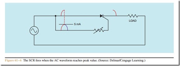
The SCR is a rectifier; when it is connected in an AC circuit, the output is direct current. The SCR operates in the same manner in an AC circuit as it does in a DC circuit. The difference in operation is caused by the AC waveform falling back to 0 at the end of each half cycle. When the AC waveform drops to 0 at the end of each half cycle, the SCR turns off. This means that the gate must retrigger the SCR for each cycle it is to conduct (Figure 61– 6).
Assume that the variable resistor connected to the gate has been adjusted to permit 5 milliampere of cur- rent to flow when the voltage applied to the anode reaches its peak value. When the SCR turns on, current will begin flowing through the load resistor when the AC waveform is at its positive peak. Current will continue to flow through the load until the decreasing voltage of the sine wave causes the current to drop below the holding current level of 100 milliampere. When the current through the anode-cathode section drops below 100 milliampere, the SCR turns off and all current flow stops. The SCR will remain turned off when the AC waveform goes into its negative half cycle because during this half cycle the SCR is reverse biased and cannot be fired.
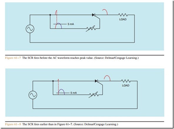
If the resistance connected in series with the gate is reduced, a current of 5 milliampere will be reached be- fore the AC waveform reaches its peak value (Figure 61– 7). This will cause the SCR to fire earlier in the
cycle. Since the SCR fires earlier in the cycle, current is permitted to flow through the load resistor for a longer period of time, which produces a higher average voltage drop across the load. If the resistance of the gate circuit is reduced again, as shown in Figure 61– 8, the 5 milliampere of gate current needed to fire the SCR will be reached earlier than in Figure 61– 7. Cur- rent will begin flowing through the load sooner than be- fore, which will permit a higher average voltage to be dropped across the load.
Notice that this circuit enables the SCR to control only half of the positive waveform. The latest the SCR can be fired in the cycle is when the AC waveform is at 90° or peak. If a lamp were used as the load for this circuit, it would burn at half brightness when the SCR first turned on. This control would permit the lamp to be operated from half brightness to full brightness, but it could not be operated at a level less than half brightness.

