The Zener Diode
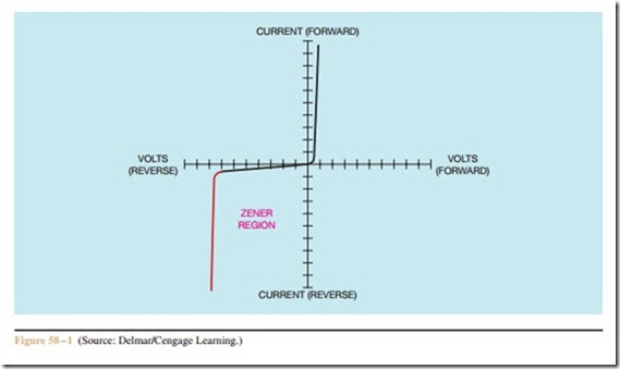
The zener diode is a special device designed to be op- erated with reverse polarity applied to it. When a diode is broken down in the reverse direction, it enters what is known as the zener region. Usually, when a diode is broken down into the zener region, it is destroyed; the zener diode, however, is designed to be operated in this region without harming the device.
When the reverse breakdown voltage of a zener diode is reached, the voltage drop of the device remains almost constant regardless of the amount of current flowing in the reverse direction (Figure 58 – 1). Since the voltage drop of the zener diode is constant, any de- vice connected parallel to the zener will have a constant voltage drop even if the current through the load is changing.
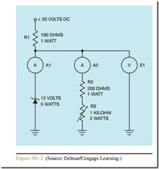
In Figure 58 – 2, resistor R1 is used to limit the to- tal current of the circuit. Resistor R2 is used to limit the current in the load circuit. Note that the value of R1 is less than the value of R2. This is to ensure that the sup- ply can furnish enough current to operate the load. Note also that the supply voltage is greater than the zener
voltage. The supply voltage must be greater than the voltage of the zener diode or the circuit cannot operate.
Resistor R1 and the zener diode form a series cir- cuit to ground. Since the zener diode has a voltage drop of 12 volts, resistor R1 has a voltage drop of 8 volts: (20 V – 12 V = 8 V). Therefore, resistor R1 will per- mit a maximum current flow in the circuit of 0.08 am- peres or 80 milliamperes:
The load circuit, which is a combination of R2 and R3, is connected parallel to the zener diode. Therefore, the voltage applied to the load circuit must be the same as the voltage dropped by the zener. If the zener diode maintains a constant 12 volt drop, a constant voltage of 12 volts must be applied to the load circuit.
The maximum current that can flow through the load circuit is 0.06 amperes or 60 milliamperes:
Notice that the value of R2 (200 ohms) is used to ensure that there is enough current available to operate the load.
The maximum current allowed into the circuit by resistor R1 is always equal to the sum of the currents passing through the zener diode and the load. For ex- ample, when the load is connected parallel to the zener diode as shown in Figure 58 – 2, and resistor R3 is ad- justed to 0 ohms, meter A1 will indicate a current of 20 milliamperes, and meter A2 will indicate a current of 60 milliamperes. Therefore, the maximum current allowed into the circuit by resistor R1 will be 80 mil- liamperes (20 mA + 60 mA = 80 mA). The voltage value indicated by meter E1 will be the same as the zener voltage value.
If resistor R3 is increased in value to 200 ohms, the resistance of the load will increase to 400 ohms (200 + 200 = 400). Meter A1 will indicate a current of 50 mil- liamperes and meter A2 will indicate a current of 30 milliamperes. The voltage value indicated by meter E1 will still be the same as the zener voltage value.
The zener diode, therefore, makes a very effective voltage regulator for the load circuit. Although the current through the load circuit changes, the zener diode forces the voltage across the load circuit to remain at a constant value, and conducts the current not used by the load circuit to ground.
The schematic symbol for a zener diode is shown in Figure 58 – 3. The zener diode can be tested with an ohmmeter in the same manner as a common junction diode is tested, provided the zener voltage is greater than the battery voltage of the ohmmeter.
1. How is a zener diode connected in a circuit as compared to a common junction diode?
2. What is the primary use of a zener diode?
3. A 5.1 volt zener diode is to be connected to an 8 volt power source. The current must be limited to 50 milliamperes. What value of current-limiting resistor must be connected in series with the zener diode?
4. How is a zener diode tested?
5. In a zener diode circuit, the current limiting resistor limits the total circuit current to 150 mil- liamperes. If the load circuit is drawing a current of 90 milliamperes, how much current is flowing through the zener diode?


