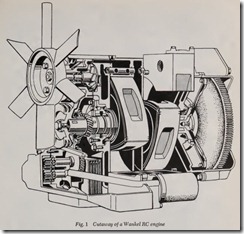
The Wankel Rotary Combustion Engine repre sents a complete departure from ordinary internal combustion engine design. Despite this fact, its operation is quite easy to understand; provided one unders tands conventional four-stroke cycle automotive engines to which it will be compared.
There is nothing mysterious about the princi ples on which the Wankel RC (rotary combus tion) engine is based. It, like all internal combus tion engines, is a machine that converts the heat energy of the fuel burned into useful mechani cal work. To accomplish this, the Wankel RC utilizes the familiar Otto-cycle as does its recipr ocating, piston engine counterpart. That is, a mixture of fuel and air is introduced into a confined chamber in an Intake phase. This mixture then has pressure put on it in a Compression phase, following this it is ignited and expands in a Power phase and, finally, burned gases are di.scharged from the chamber in an Exhaust phase.
In a piston engine these phases are called strokes and the whole sequence is described as a four-stroke cycle, after the strokes made by the piston to complete one entire cycle. In the Wankel Rotary Combustion engine the four phases cannot be described as strokes as no piston is involved so the whole conversion of heat engery into work is called by the general term, Otto-cycle process, not by the term four-stroke cycle process.
Thus, it is apparent that a major difference between the conventional four-stroke cycle auto motive engine and the Wankel RC lies in the matter of the piston or pistons. The latter engine substitutes a roughly triangular shaped rotor as a power harnessing device that, as the name of the engine implies, rotates within the working cham ber. This system dispenses with the piston and connecting rod which converts the reciprocating motion of the piston to the circular motion of the crankshaft. In short, the Wankel RC translates power directly into a circular path. This circular m otion is utilized, as is the identical circular mo tion of the crankshaft in a reciprocating engine, to propel the car.
In addition to eliminating intermediate devices such as the piston, piston pin and connecting rod, the rotary engine does not need a complicated valve system. It uses ports in the working cham ber, like the ports in the cylinder of a two-stroke cycle engine, that dispense with the complicated valve arrangement of ordinary automobile en gines. It is this simplicity, this fewer number of working parts that give the Wankel RC engine its initial potential advantage over other internal combustion engines.
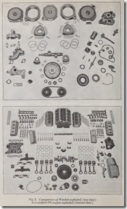
To appreciate this simplicity look at Fig. 2 which shows both a Wankel and a modern V8 piston engine disassembled. The Wankel has slightly over half as many parts. Furthermore, assembled, th e RC is considerably smaller and lighter, sometimes less than half the weight of a V8 of equivalent output.
Major Engine Components
Instead of a cylinder and piston, the rotary combustion engine uses a rotor and rotor housing. The rotor housing and a cylinder are comparable in that they both provide a working chamber for the energy conversion process to take place. In the same way , the rotor and :; piston are similar be cause they both do work on the fuel air mixture in compressing it and, in tum, have work done on them when the fuel air mixture is ignited during the power phase. Because· the rotor and the rotor hous ing entertain a circular motion during the cycle while the piston and cylinder accomodate a linear, up-a nd-down motion, the comparison is not exact. It is the step-by-step sequence of events that diff ers between the two types of engines, not the essential function of the basic components.
In a piston engine the crankshaft and flywheel furnish the pow er take-off point. Their exact coun terparts in a rotary combustion engine are the mainshaft and flywh eel. The flywheels on both engines are approxim ately the same and the crankshaft and mainshaft diff er only in that the U shaped crankshaft throw on a crankshaft becomes a solid lobe on the mainshaft. Since there are presently only one or two rotors used on auto-motive Wankel RC engines the output shaft has only one or two lobes, this is in contrast to the four throws on a VB crankshaft.
Both kinds of engines utilize closely similar fuel, cooling, lubrication, and ignition systems. Wankel RC’s have been equipped with both fuel injection devices and carburetors and either unit could be interchanged on a piston engine of the equivalent cubic inch displacement with a minimum of modi fication. The rotary engine is currently being pro duced in both water and air cooled versions (though the last named is not being used in automobiles) and the heat transfer requirements for a four-stroke engine and a Wankel of the same power output are roughly equal. Any modern ignition system is applicable to the rotary engine and lubrication requirements remain the same with one slight difference. Current Wankel en gines must have oil added to the gasoline, like a two-stroke cycle engine, or use some other method such as a metering device feeding oil into the intake to assure lubrication of the rotor seals.
Rotary Combustion Process
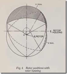
It is difficult initially to follow the sequence of events that occur in a rotary combustion engine for two reasons. First, several phases are taking place simultaneously within the rotor housing. Secondly, we are used to picturing in our minds the Otto-cycle as it takes place in a piston engine: in an up-and-down, easy to follow sequence. Ad justing to the overlapping phases and the com plicated double rotary motions of the rotor and the mainshaft requires some practice. To simplify it, consider the rotor housing as being two intersecting shallow cylinders. The three sided, triangular, rotor turns in this cavity so that its path describes a circle at the junction of the two cylinders while it rotates around its own center at the same time. Called a planetary mo tion, the effect is the same as picturing the world moving in a circular path around the sun while it also turns on its own axis.
These two distinct rotations of the rotor are timed so that each of the rotor’s three corners, called apexes, are always in contact with the walls of the rotor housing, Fig. 4.
The mainshaft is centered at the geometric mid point of the rotor housing and its lobe, or ec centric as it is known, follows the rotor as it traces its circular path around that midpoint. The output shaft makes three revolutions about its center while the rotor is making one complete turn about its center on the eccentric of the mainshaft. While the rotor makes one revolution, of course, each apex will have completely traversed the wall of the rotor housing.
To assure that there is correct motion between rotor and shaft, a gearing arrangement is provided. One gear is placed around the center of rotation of the rotor while another, smaller gear meshing with it is fixed to the mainshaft or engine housing. If these timing gears were not present
– the rotor could simply flop about or jam in the rotor housing without traversing its walls. Putting it another way, the output shaft eccentric only makes certain that the rotor describes the right motion about the shaft and does nothing to make it turn while describing that motion; this function is taken over by the timing gears.
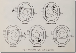
Having three sides, the rotor allows three com plete combustion processes composed of four phases each, to take place while it makes a single traverse of the rotor housing wall, Fig. 5. There fore, each of the rotor sides acts as a movable combustion chamber providing, successively, in take, compression, power and exhaust phases. By studying the size of this “combustion chamber” space as the rotor turns it is easy to see that its volume changes just as its equal number in a cylinder does as the piston moves up and down. But, it will be noticed that by watching all three “combustion chambers” various different phases of the cycle are occurring in each of the three. Never, of course, are the same phases taking place in more than one of the three chambers at the same oment. At this point, the individual phases can be studied as they occur.
Intake Phase
Direction of rotation of the rotor shown in Fig. 5 is clockwise. Looking at one flank of the rotor, indicated by the black arrow, it can be seen that apex A began the intake phase by uncovering the intake port in the side of the rotor housing. The chamber under consideration is that delineated by the rotor flank AB and it is almost at its maximum volume when it is in the position shown over the heading INTAKE. In this position the chamber can be compared to a cylinder with the piston approaching bottom dead center on the intake stroke.
Notice that the fuel-air mixture entered the chamber through the port in the side of the rotor housing. This type is called a side port and con trasts with the peripheral type which is set in the rotor housing wall, as per the lower port shown over the heading EXHAUST. Some engines use both a side and peripheral port or a pair of peripheral ports, with one or the other opened by means of a butterfly valve only during high speed operation. The port which is open at all times is called the primary, the other, the secondary. It is characteristic of the Wankel RC engine that inlet (volumetric) efficiency can be made almost ideal. This is so because practically any port size and shape can be accomodated in the rotor housing of a particular engine. Timing of the intake port, its location with respect to the center line of the rotor housing on its short axis, unfortunately can not be varied greatly without sacrificing performance in certain speed ranges.
Compression Phase
During compression, chamber size is gradually decreased as can be seen by comparing chamber volum e over the headings, INTAKE and COM PRESSION in Fig. 5. Comparison of the chamber volume between its m aximum, slightly more than shown over INTAKE, and minimum, that shown over IGNITION, is the compression ratio. It is exactly comparable to the compression ratio of a four-stroke cycle engine as obtained when cylin der volume with the pisto n at bottom dead center is divided by cylind er volume with the piston at top dead center.
Compression ratio of an RC engine is controlled by engine geometry and a great variety of differ ent ratios have been experimented with. In gen eral, compression ratios on production Wankel engines are about the same as those used on pist on engines, usu ally betwe en 8.5 and 10.5 to 1. But, it should be noted in this respect that Wankel en gines do not seem to be as demanding in the matter of octane requirements and engines with high compression ‘ratios ( 10:1) run well on regu lar gasoline.
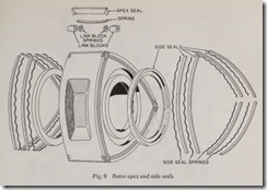
Not shown in Fig. 5 but present on an actual engine are the seals that contain gas pressure within the chambers. Apex seals run across the edges of the three apexes, A, B & C and ride against the rotor housing wall to prevent gas leakage at thos e points between adjacent cham bers. Side seals are set in th e flanks of the rotor, just in from the edges, and ride against the sides of the rotor housing. Serving the same function as piston rings, these seals have been the source of endless difficulty in earlier Wankel engines. Pres ently, most problems with them seem to have been overcome and good service life is predicted.
Power Phase
With the rotor as shown over the heading IG NITIO N in Fig. 5, the spark plug fires and the fuel-air charge is ignited. This position of the rotor, by direct analogy with the piston of a reciprocating engine, is known as top dead center. During subsequent mo vement of the rotor, from IGNITION to EXPA NSION in Fig. 5, work is done on the rotor by the expanding gas, the entire process being called the power phase.
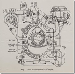
It will be appreciated that pressure applied by the expanding gas is transmitted through the rotor to the eccentric and then to the mainshaft. In this, the eccentric on the mainshaft, not shown in Fig. 5, but represented by the crescent shaped space between the rotor and mainshaft, acts in every way like the throw on a piston engine crankshaft in transmitting power. The phasing gears, one of which surrounds the rotor center opening and the other attached to the mainshaft or engine housing and meshing with it, do not transmit power. They are there simply to assure correct relative motion between mainshaft and rotor. To transmit power from the rotor to the mainshaft, either a roller or plain bearing is fitted to the eccentric where it mates with the rotor, Fig. 7.
The spark plug shown in Fig. 5, can be posi tioned in any of several locations. Unlike a piston engine, spark plug location is not over critical and it is generally placed either slightly before or slightly after the top dead center point of the rotor. That is, it is just above or just below the short axis of the rotor housing. In some cases two spark plugs are fitted, one in each of the positions noted. The plug or plugs usually fire at or near top dead center at idle and a spark advance is pro vided, just as on a piston engine, to fire them earlier and earlier as engine speed increases.
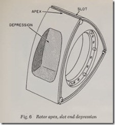
The spark plug can be set almost flush with the rotor housing wall or inset into a small pocket, as shown in Fig. 5. Usually the rotor flanks ha e de pressions, as shown in Fig. 6, that increase cham ber volume over that provided between the rotor and rotor housing wall.
Up to this point we have been concentrating our attention on one single chamber, that one confined by the rotor flank between apexes A and B. If you consider the other two flanks BC and
CA, it can be seen that their chambers have also been going through separate phases of the Otto cycle. Chamber BC being one phase behind AB and chamber CA being one phase ahead. There fore, the spark plug must fire three times for every revolution of the rotor.
Exhaust Phase
As soon as rotor apex A passes over the exhaust port the exhaust phase begins. Because of the rela tively high gas pressure in the chamber, as in the cylinder of a four-stroke or two-stroke cycle en gine with the piston well down on the power stroke, a fairly small port is adequate to exhaust the burned charge. For this reason double ports, as often used on the intake, are unnecessary.
Timing of the exhaust phase in relation to the power phase is determined by the position of the port in the rotor housing wall. With a clockwise rotor motion, as in Fig. 5, placing the port f urther down, counterclockwise, on the housing wall al lows earlier beginning of the exhaust phase and vice versa. Likewise, varying the position of the intake port or ports has the same effect on the timing of the intake phase. Four-stroke cycle en gine intake and exhaust timing, of course, are de termined by the design of the camshaft while two stroke cycle engines accomplish this timing in very much the same way as the Wankel, by locating the ports at certain points along the cylinder wall with respect to piston travel.
Here the similarities with other positive displace ment internal combustion engines cease and it can be readily seen that both intake and exhaust ports of a Wankel RC engine are open at all times. Passage of an apex over either port simply con fines gas flow to one particular chamber; it does not shut off a port set in the rotor housing wall (side inlet ports are momentarily shut off by the rotor apexes). This feature is considered to be very advantageous and means that exhaust flow out of and intake flow into a rotary combustion engine are different from the same processes in a piston engine. Despite this, a normal automotive exhaust silencer (muffler) and intake silencer (air cleaner) are sufficient to keep Wankel engines quiet.
Before leaving the subject of the energy conver sion process, it would be wise to note another unique feature of the Wankel engine. By compar ing the positions of the mainshaft index mark in Fig. 5, it is obvious that each phase of the Otto cycle extends over 270 degrees of mainshaft ro tation. This could also be determined by noting that the mainshaft makes three revolutions to one turn of the rotor and during this period the four phases of the Otto-cycle have been completed:
The strokes of a four-stroke cycle piston engine, on the other hand, occupy 180 degrees of crank shaft rotation, from top dead center of piston travel to bottom dead center or vice versa.
Engine Construction
Wanke1 RC engines are made of common ma terials such as those used in ordinary automobile engines and they do not require exotic or unusual alloys. While many different materials have been tried for the different components, aluminum al loys, cast iron, and various grades of steel are generally preferred.
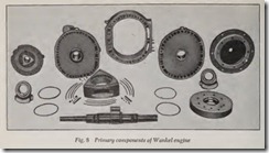
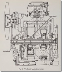
The engine consists, in a one rotor version, of six or more primary components, Fig. 8. A main shaft mounts the rotor, which is in turn contained within a separate rotor housing. The rotor housing is bolted between two end covers and the align ment between them, which is very critical, is maintained by dowel pins. The mainshaft projects out of both end covers where it is supported by ball, roller or plain bearings. One or two flywheels are fitted to the projecting stubs and these fly wheels are not symetrically weighted as on a four stroke cycle engine. Since the mainshaft does not use counterbalance weights to offset the mass of the eccentric or rotor, these must be provided for in the disc shaped but unevenly weighted fly wheel. These flywheels have a ring gear to ac commodate the starter motor.
Additional rotors are accommodated by adding the rotor and its appropriate rotor housing plus an intervening spacer that separates the two hous ings. This spacer projects down to the mainshaft but does not have to support it after the fashion of an intermediate web with its main bearing in a piston engine. The mainshafts arc very short and stiff so they do not require support at this point. When multi-rotor engines are built, units with up to four rotors have been built though not for automotive use, they are assembled out of com ponents which are used for single rotor construc tion. This saves design and production time and cost and provides for a family of engines of differ ent displacements and power outputs but with the same basic components.
The critical parts of the Wankel engine design are the bore of the rotor housing, the rotor itself, and the rotor seals. From design and manufactur ing viewpoints it can be appreciated that the bore configuration, its shape called an epitrochoid, and the shape of the rotor present problems.
From the performance viewpoint, it is the rotor housing bore and the rotor seals that give the most trouble. Rapid seal wear, the wear problem with seals is much more complex than it is with the corresponding piston rings of a reciprocating en gine, plagued the acceptance of the engine for years. When harder apex seals were used to lessen wear, they left chatter marks on the wall of the rotor housing.
Presently, a number of different solutions have been proposed and several adopted to overcome these twin problems. Some manufacturers utilize a hard coating on the rotor housing wall while others vary the materials out of which the seals are made as well as the design of the seals them selves. All engines in production are claimed to have largely eliminated the two problems or at least brought them under control to the point that seal wear and bore chatter can be kept to safe limits.
Engine Performance
Positive displacement engines such as recipro cating piston or rotary combustion types are com pared on the volume of air they displace. This figure is considered to represent the potential each engine possesses for power development, although it docs not enter into power development calcula tions themselves. The idea is that the higher an engines displacement is, the more horsepower it is theoretically capable of producing.
To obtain this figure for a reciprocating engine, the volume contained in one cylinder with the piston at bottom dead center is multiplied by the number of cylinders. Both two and four stroke cycle engines arc calculated in the same way, but, because a two-stroke has twice as many power strokes it should ideally produce twice the power of a four-stroke with the same displacement. This has been the source of endless controversy among engineers becaus’e of this fact and many therefore feel that displacement is not a good basis of com parison between the potentials of various engines . Nevertheless, it is still used. Enter the Wankel RC. It further compounds the problem because its potential power output is seemingly even less re lated to displacement than is the power output of a two-stroke cycle piston engine. Furthermore, not many engineers agree on how the comparative displacement of Wankel should be calculated.
One widely used method of obtaining this fig ure follows. It is based on the notion that since a single rotor Wankel engine completes two energy conversion cycles during two rotations of the mainshaft, it has the power potential of a two stroke cycle engine. Thus, a double rotor Wankel RC has a displacement equivalent, in terms of crankshaft rotation, to a four-stroke cycle, four cylinder piston engine if the volume of one Wankel chamber is the same as the volume of one cylinder of the piston engine.
The International Automobile Federation (the FIA, the sanctioning body for international auto racing), therefore, determines rotary combustion engine displacement by doubling the volume of one chamber and multiplying that figure by the number of rotors. For example, if a certain Wankel RC engine has a chamber volume of 60 cubic inches, its displacement would be:
2 X 60 cu. in. X 2 (number of rotors) = 240 cu. in.
Of course, not all companies producing Wankel engines subscribe to this method, so when dis placement figures are compared it is necessary to find out how the Wankel determination was made.
Whether displacement or some other means of comparison is used, Wankel RC engine efficiency and performance at present are roughly equiva lent to four-stroke cycle engines.
Potential performance to be realized with fur ther development of the Wankel is, however, an other matter. Consideration of the three basic efficiencies of an internal combustion engine, namely, thermal, volumetric, and mechanical, in dicates where this potential might lead.
The thermal efficiency of either a Wankel or a four-stroke cycle engine is to a large extent deter mined by the compression ratio. It seems that future rotary combustion engines will tolerate higher compression ratios than will their oppo site number piston engines because of lower fuel octane requirements. Another factor of perfor mance related to thermal efficiency is engine speed.
Without inertia eff ects of a complicated valve arrangement or reciprocatin g parts, the Wankel engine should tolerate considerably higher ro tating speeds than presently employed.
Volumetric efficien cy, or “breathing” of the Wankel is already high because of their porting layout and other considerations. So is mechanical efficiency because of th e Wankels fewer number of moving parts.
Presently, the RC engines strongest claim islarge output from a small, simple and conse quently light pa ckage. This, coupled with low manufacturing cost, one estimate lists manufactur ing costs for an RC at $1.00 per pound of engine weight ver sus $2.00 per pou nd for a modern V8, are the prin cipal attractions of this new engine.
Developme nt of the Engine
Considering their recent invention , rotary com bustion engines have been developed to an amaz ing degree. While the piston type internal com bu stion engine has had about nin ety years in which to develop, th e first workin g model w as demonstrated by Dr. Nicholas Otto in 1878, the rotary combustion engine has had less than fif teen. While it is true that the concept of a rotary combu stion engine has been around since the early part of this century, it rem ained for Dr. Felix Wankel of Lindau, Germany, to first successfully test such a machine in 1957. It is not surprising, then, that the Wankel RC en gine has not yet realized as much of its potential as has the re ciprocating engine.
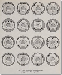
Other kinds of rotary machines such as wind mills no doubt furnished the inspiration for the idea of a rotary combustion engine. Dr. Wankel, taking that idea from early experimenters, sys tematically investigated most of the possibl e con figurations, Fig. 3 shows a few of the hundreds of possible designs, over a long period before he con ceived and began laying out his first engine in 1954. Early collaborating with the Germ an car company, NSU, he had built several engines by the end of 1957. The final ver sion, with a modest displacement of 7.6 cu. in., develope d an astonish ing 29 hp at 17,000 rpm in a 100 hour test.
The early engine was decidedly diff erent from current examples in that the rotor housing also turned and was contained within a larger sta tionary housing . Called the SIM type, this engine’s rotor turned but did not transmit pow er. The turning rotor housing accomplished this through gearing to an output shaft. The complexity of the engine can be appreciated when it is realized that the turning rotor also held the three spark plugs required together with their leads and that the hollow rotor shaft also served as the fuel-air intake pipe.
A machine similar in most respects to the SIM, but driven as a compressor by outside means, was used as a supercharger by NSU. Fitted to a mo torcycle, the supercharger helped the engine pro duce the equivalent of 260 hp per 61 cu. in. If this kind of performance could be coaxed from a modern V8, a 283 cu. in. version would produce over 1200 hp.
NSU also contributed much in helping to sim plify the original Wankel RC engines. It was with their help that Dr. Wankel redesigned the engine to the less complicated form we know today, called the PLM or planetary rotation engine. The PLM type Wankel engines are being produced under license or tested in most of the automobile making countries of the world. Cars made by NSU in Germany and Toyo Kogyo in Japan are equipped with Wankel R’s and Curtiss-Wright Corp., the licensee in the U.S.A., is far along in the development of several models for automobile, truck, aircraft and industrial use.
Engine Specifications
Manufacturer ………… Toyo Kogyo (Japan)
Car ……………………………. Mazda
Engine Model ………….. UOS, Wankel RC
Rotors ………….. 2
Brake Horsepower . 123 @ 7000 RPM (mainshaft)
Torque . . . 96.2 lb. ft. @ 3500 RPM ( mainshaft)
Equivalent Displacement . . . . . . . . . . 120.5 cu. in.
Compression Ratio . . . . . . . . . . 9.4:1
Mainshaft Eccentricity . . . . . . . . . . . . . . . . 0.59 in.
Cooling ………….. Water, rotors oil cooled
Carburetor ………… 1 Stromberg four-barrel
Ignition …….. Coil with 2 spark plugs per rotor
Weight ……………. 225 lbs w/water & oil
Power: Weight Ratio ………. 0.48 HP per lb.
Length . . . . . . . . . . . . . . . . . . . . . . . . . . . . . 20.08 in.
Width . . . . . . . . . . . . . . . . . . . . . . . . . . . . . . 23.43 in.
Height . . . . . . . . . . . . . . . . . . . . . . . . . . . . . 21.65 in.
Ports ………….. 1exhaust, 2 intake per rotor
Review Questions
|
1. Why can’t the four phases of operation in the Wankel engine be described as strokes? …. |
|
2. What is the proper name for the operating cycle used in both the Wankel and the common reci.procati.ng engm. e.? . …………………………………………………. . |
|
3. What is the main difference between the conventional engine and the Wankel? ……… . |
|
4. What is the Wankel’s initial advantage over other internal combustion engines? …….. . |
|
5. What are the major components of the Wankel? …………………………….. . |
|
6. How does the Wankel work? ……………………………………………. . |
|
7. How are valves eliminated in the Wankel? ……….. . ………………………. . |
|
8. How is it that, in the Wankel, inlet efficiency can be almost ideal? ……………….. . |
|
9. How is the compression ratio controlled in the Wankel? ……………………….. . |
|
10. In the Wankel, what parts serve the same function as the piston rings in a conventional |
|
engine? ………………………………….. ‘” ……………………….. . |
|
11. Is spark plug location very critical in the Wankel? …………………………… . |
|
12. How is the exhaust phase timing accomplished in the Wankel? …… …………….. . |
|
13. What materials are preferred in the construction of the Wankel? ………………… . |
|
14. At what point in the Wankel is wear a major problem? ………………………… . |
15. How does the performance of the Wankel compare with that of other types of engines? ..
