Sampling and Quantizing
It is not possible to introduce each element of this broad topic without requiring the reader to have some foreknowledge of future topics. The aforementioned text has tacitly admitted that you will wish to match the description of the processes involved to a digitized audio signal, although we have pointed out that handling audio signals in the digital domain is only an example of some of the flexibility of digital signal processing.
The process of converting an analogue audio signal into a sequence of sample values requires two key operations. These are sampling and quantization. They are not the same operation, for while sampling means that we only wish to consider the value of a signal at a fixed point in time, the act of quantizing collapses a group of amplitudes to one of a set of unique values. Changes in the analogue signal between sample points are ignored. For both of these processes the practical deviations from the ideal process are reflected in different ways in the errors of conversion.
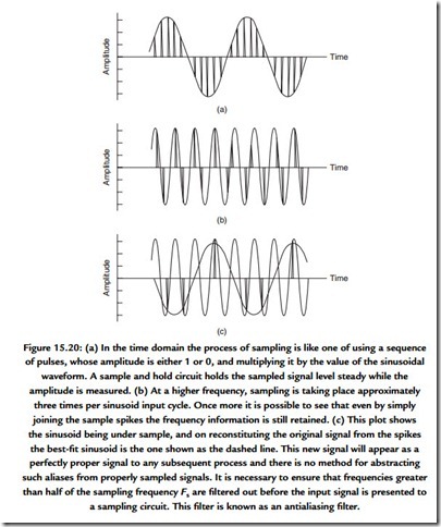
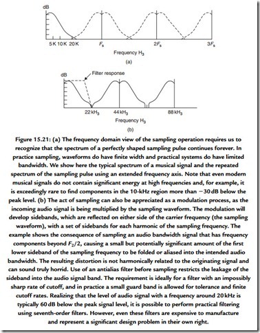
Successful sampling depends on ensuring that the signal is sampled at a frequency at least twice that of the highest frequency component. This is Nyquist’s sampling theorem. Figure 15.20 shows the time domain view of the operation, whereas Figure 15.21 shows the frequency domain view.
Sampling
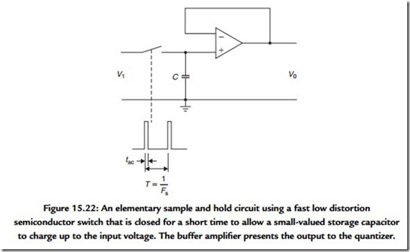
Practical circuitry for sampling is complicated by the need to engineer ways around the various practical difficulties. The simple form of the circuit is shown in Figure 15.22. The analogue switch is opened for a very short period, tac each 1/Fs seconds. In this short period the capacitor must charge (or discharge) to match the value of the instantaneous input voltage. The buffer amplifier presents this voltage to the input of the quantizer or analogue-digital converter (ADC). There are several problems. The series resistance of the switch sets a limit on how large the storage capacitor can be while the input current requirements of the buffer amplifier set a limit on how low the capacitance can be. The
imperfections of the switch mean that there can be significant energy leaking from the switching waveform as the switch is operated and there is the problem of cross talk from the audio signal across the switch when it is opened. The buffer amplifier itself must be capable of responding to a step input and settling to the required accuracy within a small fraction of the overall sample period. The constancy or jitter of the sampling pulse must be kept within very tight tolerances and the switch itself must open and close in exactly the same way each time it is operated. Finally, the choice of capacitor material is itself important because certain materials exhibit significant dielectric absorption.
The overall requirement for accuracy depends greatly on the acceptable signal-to-noise ratio (SNR) for the process, which is much controlled by the resolution and accuracy of the quantizer or converter. For audio purposes we may assume that suitable values for Fs will be in the 44- to 48-kHz range. The jitter or aperture uncertainty will need to be in the region of 120 pse, acquisition and settling time need to be around 1 μs, and the capacitor discharge rate around 1 V/s for a signal that will be quantized to 16 bits if the error due to that cause is not to exceed +/- 0.5 LSB. The jitter performance is complex to visualize completely because of the varying amplitude and frequency component of the jitter itself.
At this stage you will need to be sure you are confident that you appreciate that the combined effect of the antialias filtering and the proper implementation of the sampling process mean that sampled data contain perfectly all of the detail up to the highest frequency component in the signal permitted by the action of the antialias filter.


