TORQUE PRODUCTION
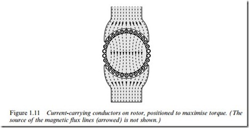
Having designed the magnetic circuit to give a high Xux density under the poles, we must obtain maximum beneWt from it. We therefore need to arrange a set of conductors, Wxed to the rotor, as shown in Figure 1.11, and to ensure that conductors under a N-pole (at the top of Figure 1.11) carry positive current (into the paper), while those under the S-pole carry negative current. The tangential electromagnetic (‘BIl ’) force (see equation 1.2) on all the positive conductors will be to the left, while the force on the negative ones will be to the right. A nett couple, or torque will therefore be exerted on the rotor, which will be caused to rotate.
(The observant reader spotting that some of the conductors appear to have no current in them will Wnd the explanation later, in Chapter 3.)
At this point we should pause and address three questions that often crop up when these ideas are being developed. The Wrst is to ask why we have made no reference to the magnetic Weld produced by the current- carrying conductors on the rotor. Surely they too will produce a mag- netic Weld, which will presumably interfere with the original Weld in the air-gap, in which case perhaps the expression used to calculate the force on the conductor will no longer be valid.
The answer to this very perceptive question is that the Weld produced
by the current-carrying conductors on the rotor certainly will modify the original Weld (i.e. the Weld that was present when there was no current in the rotor conductors.) But in the majority of motors, the force on the conductor can be calculated correctly from the product of the current and the ‘original’ Weld. This is very fortunate from the point of view of calculating the force, but also has a logical feel to it. For example in Figure 1.1, we would not expect any force on the current-carrying conductor if there was no externally applied Weld, even though the current in the conductor will produce its own Weld (upwards on one side of the conductor and downwards on the other). So it seems right that since we only obtain a force when there is an external Weld, all of the force must be due to that Weld alone.
The second question arises when we think about the action and reaction principle. When there is a torque on the rotor, there is presumably an equal and opposite torque on the stator; and therefore we might wonder if the mechanism of torque production could be pictured using the same ideas as we used for obtaining the rotor torque. The answer is yes; there is always an equal and opposite torque on the stator, which is why it is usually important to bolt a motor down securely. In some machines (e.g. the induction motor) it is easy to see that torque is produced on the stator by the interaction of the air-gap Xux density and the stator currents, in exactly the same way that the Xux density interacts with the rotor currents to produce torque on the rotor. In other motors, (e.g. the d.c. motor we have been looking at), there is no simple physical argument which can be advanced to derive the torque on the stator, but nevertheless it is equal and opposite to the torque on the rotor.
The Wnal question relates to the similarity between the set-up shown in Figure 1.10 and the Weld patterns produced for example by the electro- magnets used to lift car bodies in a scrap yard. From what we know of the large force of attraction that lifting magnets can produce, might not we expect a large radial force between the stator pole and the iron body of the rotor? And if there is, what is to prevent the rotor from being pulled across to the stator?
Again the aYrmative answer is that there is indeed a radial force due to magnetic attraction, exactly as in a lifting magnet or relay, although the mechanism whereby the magnetic Weld exerts a pull as it enters iron or steel is entirely diVerent from the ‘BIl ’ force we have been looking at so far.
It turns out that the force of attraction per unit area of pole-face is proportional to the square of the radial Xux density, and with typical air- gap Xux densities of up to 1 T in motors, the force per unit area of rotor surface works out to be about 40 N=cm2. This indicates that the total radial force can be very large: for example the force of attraction on a small pole-face of only 5 x 10 cm is 2000 N, or about 200 Kg. This force contributes nothing to the torque of the motor, and is merely an unwelcome by-product of the ‘BIl ’ mechanism we employ to produce tangential force on the rotor conductors.
In most machines the radial magnetic force under each pole is actually a good deal bigger than the tangential electromagnetic force on the rotor conductors, and as the question implies, it tends to pull the rotor onto the pole. However, the majority of motors are constructed with an even number of poles equally spaced around the rotor, and the Xux density in each pole is the same, so that – in theory at least – the resultant force on the complete rotor is zero. In practice, even a small eccentricity will cause the Weld to be stronger under the poles where the air-gap is smaller, and this will give rise to an unbalanced pull, resulting in noisy running and rapid bearing wear.
Magnitude of torque
Returning to our original discussion, the force on each conductor is given by equation 1.2, and it follows that the total tangential force F depends on the Xux density produced by the Weld winding, the number of conductors on the rotor, the current in each, and the length of the rotor. The resultant torque or couple1 (T) depends on the radius of the rotor (r), and is given by
We will develop this further in Section 1.5, after we examine the remark- able beneWts gained by putting the conductors into slots.
The beauty of slotting
If the conductors were mounted on the surface of the rotor iron, as in Figure 1.11, the air-gap would have to be at least equal to the wire diameter, and the conductors would have to be secured to the rotor in order to transmit their turning force to it. The earliest motors were made like this, with string or tape to bind the conductors to the rotor.
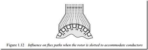
Unfortunately, a large air-gap results in an unwelcome high-reluctance in the magnetic circuit, and the Weld winding therefore needs many turns and a high current to produce the desired Xux density in the air-gap. This means that the Weld winding becomes very bulky and consumes a lot of power. The early (Nineteenth-century) pioneers soon hit upon the idea of partially sinking the conductors on the rotor into grooves machined parallel to the shaft, the intention being to allow the air-gap to be reduced so that the exciting windings could be smaller. This worked extremely well as it also provided a more positive location for the rotor conductors, and thus allowed the force on them to be transmitted to the body of the rotor. Before long the conductors began to be recessed into ever deeper slots until Wnally (see Figure 1.12) they no longer stood proud of the rotor surface and the air-gap could be made as small as was consistent with the need for mechanical clearances between the rotor and the stator. The new ‘slotted’ machines worked very well, and their pragmatic makers were unconcerned by rumblings of discontent from sceptical theorists.
1 Older readers will probably have learned the terms Couple and Moment (of a force) long before realising that they mean the same as torque.
The theorists of the time accepted that sinking conductors into slots allowed the air-gap to be made small, but argued that, as can be seen from Figure 1.12, almost all the Xux would now pass down the attractive low-reluctance path through the teeth, leaving the conductors exposed to the very low leakage Xux density in the slots. Surely, they argued, little or no ‘BIl ’ force would be developed on the conductors, since they would only be exposed to a very low Xux density.
The sceptics were right in that the Xux does indeed Xow down the teeth; but there was no denying that motors with slotted rotors produced the same torque as those with the conductors in the air-gap, provided that the average Xux densities at the rotor surface were the same. So what could explain this seemingly too good to be true situation?
The search for an explanation preoccupied some of the leading thinkers long after slotting became the norm, but Wnally it became possible to verify theoretically that the total force remains the same as it would have been if the conductors were actually in the Xux, but almost all of the tangential force now acts on the rotor teeth, rather than on the conductors themselves.
This is remarkably good news. By putting the conductors in slots, we simultaneously enable the reluctance of the magnetic circuit to be re- duced, and transfer the force from the conductors themselves to the sides of the iron teeth, which are robust and well able to transmit the resulting torque to the shaft. A further beneWt is that the insulation around the conductors no longer has to transmit the tangential forces to the rotor, and its mechanical properties are thus less critical. Seldom can tentative experiments with one aim have yielded rewarding outcomes in almost every other relevant direction.
There are some snags, however. To maximise the torque, we will want as much current as possible in the rotor conductors. Naturally we will work the copper at the highest practicable current density (typically between 2 and 8 A=mm2), but we will also want to maximise the cross-
sectional area of the slots to accommodate as much copper as possible. This will push us in the direction of wide slots, and hence narrow teeth. But we recall that the Xux has to pass radially down the teeth, so if we make the teeth too narrow, the iron in the teeth will saturate, and lead to a poor magnetic circuit. There is also the possibility of increasing the depth of the slots, but this cannot be taken too far or the centre region of the rotor iron – which has to carry the Xux from one pole to another – will become so depleted that it too will saturate.
In the next section we look at what determines the torque that can be obtained from a rotor of a given size, and see how speed plays a key role in determining the power output.

