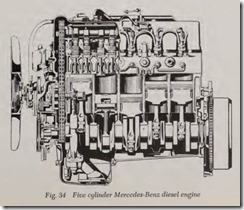
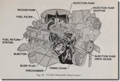
Traditionally, automobile diesel engines have been 4-cylinder powerplants. For various reasons, the latest diesel engines have broken with that tradition. We’ve recently seen the introduction of a 5-cylinder diesel from Mercedes-Benz and a V8 diesel from the Oldsmobile Division of General Motors.
MERCEDES-BENZ 5-CYLINDER
The goal in designing the 300D 5-cylinder en gine, Fig. 34, was to gain more power for better acceleration, without sacrificing fuel economy. Within present technology and cost parameters, the best way to increase light-duty passenger car diesel engine output is through an increase in pis ton displacement. Since the individual cylinder volume of Mercedes-Benz’s 240D 4-cylinder diesel engine, at 600cc ( 36.6 cu. in.), was considered the maximum for optimum combustion efficiency with the Mercedes-Benz pre-chamber system, the build ing of a larger displacement 4-cylinder engine was ruled out. On the other hand, an inline 6-cylinder diesel was considered too large and too heavy be cause of structural requirements. The solution was the addition of another cylinder to the 240D engine.
Engine bore, stroke, combustion chamber de sign, valve sizes and injection timing was the same for both the 240D and the 300D. Many parts, such as pistons, connecting rods, valves, rocker arms, bearings and injector nozzles were inter changeable. The block, oil pan, cylinder head, crankshaft (with six main bearings and vibration damper), camshaft (overhead) and oil pump were designed for the addition of the fifth cylinder. The dimensions of the cylinder head pre-chamber were changed slightly.
At 515 pounds, the weight of the 5-cylinder engine roughly corresponded to that of the 2.8- liter, 6-cylinder gas engine. It was 68 pounds heav ier than the 240D engine.
The new 3.0-liter engine ( 183.4 cu. in.) devel oped 77 HP (net) at 4000 RPM and 115 lbs. ft. of torque (net) at 2400 RPM. Max. engine speed was governed at 4350 RPM. Despite the 24% in crease in net horsepower over the 240D, fuel con sumption was nearly identical for both.
For further reduction of hydrocarbon emissions and a small improvement in mileage, the 300D in jection pump was fitted with reverse flow damp ing valves. These valves are one way valves that prevent a small “afterspray” of fuel following the main injection pulse due to the reflected pressure wave in the line between the pump and the nozzle. Later versions of the 240D also were fitted with the reverse flow damping valves.
300D emission values were as follows: 0.23 grams/mile HC, 1.43 grams/mile CO and 1.55 grams/mile NOx. And, of course, no catalysts were used on either the 300D or 240D.
The 300D injector pump was a new develop ment, utilizing a mechanical governor and vac uum-controlled engine shutoff. This was the exact opposite of the previous arrangement, which had a vacuum governor and mechanical shutoff. The mechanical governor resulted in smoother driving characteristics and better engine control during shifting with an automatic transmission. Mechani cal governing enabled the throttle butterfly to be eliminated. The accelerator pedal was connected directly to the governor.
Mechanical governing also made it possible to use a paper air filter element instead of an oil bath type. This was due to the fact that vacuum changes in the intake manifold due to clogging of the filter did not affect governing.
The most noticeable change, especially for ex perienced diesel drivers, was the new key start and-stop system which combined pre-glowing, starting and stopping, eliminating the pull-push knob. When the key was turned to the driving position, an orange control lamp in the instrument cluster lit up and pre-glowing took place auto matically. This system was then applied to future 240D models.
When the light went out, the engine could be started by turning the key in the normal manner. The duration of the pre-glowing, which depends on the temperature of the coolant water in the cylinder head, was timed automatically. A safety device limited it to a maximum of minutes.
For stopping, moving the key to the “off” posi tion operated a vacuum control valve via a cam in the steering lock. The valve connects the stop mechanism with the brake system vacuum booster. Thus, the control rod was puHed to the stop position.
To achieve steady temperatures of the engine, especially in short-distance operation and city traffic and to further improve engine durability, the capacities of the thermostat and the water pump were increased. The thermostat, as in the 240D, was located at the water inlet to the engine.
The radiator was also larger and was combined with an oil cooler, which was bypassed until the oil temperature was over 200° F. The bypass was a thermostatic valve in the oil filter head.
In order to guarantee adequate cooling in ex treme conditions and to save horsepower, a tem perature-controlled viscous-drive fan was installed.
The engine was attached to the subframe and floor unit by three rubber mounts. To further re duce engine vibrations in the passenger compart ment, two special shock absorbers were installed between the engine mounts and the subframe.
Vibrations were a particular problem, not only because the new 3-liter engine was a diesel but because it was a 5-cylinder engine. An inline 5-cylinder engine is inherently plagued with im balanced moments of both the first and second order, whereas even in a 4-cylinder engine there is no first order imbalance. The only refinement advantage that a 5-cylinder can claim for itself is that of additional torque output.
Consequently, the development of the engine and its mountings required a lot of work. The crankshaft itself, with its throws at 72°, had four balance weights and a sh·aightforward torsional vibration damper, the results of more or less rou tine development work.
The weight and position of the crankshaft coun terweights had to be chosen so that the first and second order imbalance could be absorbed in all driving conditions by appropriately designed rub ber engine mountings. The mountings also re quired extensive development, and the two located at either side of the cylinder block incorporated a small hydraulic tube damper.
Another importa:t;J.t point in obtaining the re quired running refinement was to increase the rigidity of the bellhousing and gearbox in the ver tical plane running along the centerline of the car, a requirement that necessitated a modification in the shape of the gearbox bousing. This was not specific to the 5-cylinder engine, however, and had already been carded out on the 240D. Before it was dropped into the car, the engine was balanced as a whole. It’s also worth noting that, as in all Mercedes-Benz cars, the two-piece driveshaft and its central bearing mounting were specifically tuned to suit the particular type of engine and reduce resonance periods.
OLDSMOBILE 350 VS
Beginning with the 1978 model year, the Olds mobile Division of General Motors offered a 350 cubic inch ( 5.7 liter) diesel engine, Fig. 35, for use in the Division’s B-body and C-body (full size) models. The engine was also offered as an option in some Chevrolet and GMC light duty trucks.
The new diesel engine shared many dimensions with the 350 cid gasoline V8, which provided the starting point for the diesel conversion.
The compression ratio in the diesel was nearly three times that of the gasoline engine at 22.3 to 1. This compression ratio was also higher than other production automotive diesel engines, most of which had compression ratios of 21 or 22 to 1. So most of the major components of the diesel had to be strengthened, including block, crank, camshaft, rods and lifters.
The major difference between the gasoline and diesel 350 V8 engines was the diesel’s fuel injec tion system. The fuel injection pump, of course, controlled ignition by timing and metering the amount of fuel delivered to each cylinder. The Olds diesel used a rotary-type injection pump which performed the functions of both the dis tributor and carburetor in the gasoline engine. The timing of the injection pump was permanently set at the factory.
The fuel was delivered to the pre-combustion chamber located in the cylinder head. Ignition started in this pre-chamber, which was added to minimize emissions, noise, and smoke. A glow plug
was used to assist in cold starting. Dual 12-volt batteries provided the heat source for the glow plugs and the additional power necessary for cranking this high compression engine.
The diesel glow period, or “wait-to-start,” ranged from a few seconds on a warm day to 60 seconds or more at subzero temperatures. The en gine used Number Two diesel fuel above 20° F and Number One below 20° F.
The “wait-to-start” pe1iod was monitored by an electronic device that signaled the driver when the engine was ready to start. The “Wait” light in the instrument cluster was shut off and the “Start” light turned on.
A small diaphragm vacuum pump powered by the camshaft was added because diesel engines produce minimal manifold vacuum. This vacuum pump supplies the necessary vacuum to operate the servos for heater, air conditioning, and cruise control.
A hydraulic brake booster used in conjunction with the power steering pump powered the hy draulic assisted brakes.
In summary, except for the fact that the engine was based on a 90-degree V8 cylinder block, the rest of the engine was quite conventional in design.

