Objectives
After studying this unit, the student will be able to:
• State why reduced current starting is important
• Describe the construction and operation of primary resistor starters
• Interpret and draw diagrams for primary resistor starters
• Connect squirrel cage motors to primary resistor starters
Troubleshoot electrical problems on primary resistor starters
PRIMARY RESISTOR- TYPE STARTERS
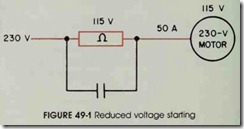
A simple and common method of starting a motor at reduced voltage is used in primary resis tor-type starters. In this method, a resistor is con nected in series in the lines to the motor, figure 49-1. Thus, there is a voltage drop across the re sistors and the voltage is reduced at the motor ter minals. Reduced motor starting speed and current are the result. As the motor accelerates, the cur rent through the resistor decreases, reducing the voltage drop (E = IR) and increasing the voltage across the motor terminals. A smooth acceleration is obtained with gradually increasing torque and voltage.
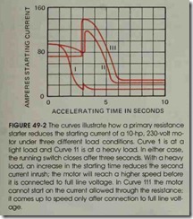
The resistance is disconnected when the motor reaches a certain speed. The motor is then con nected to run on full line voltage, figure 49-2. The introduction and removal of resistance in the mo tor starting circuit may be accomplished manually or automatically.
Primary resistor starters are used to start squirrel cage motors in situations where limited torque is required to prevent damage to driven machinery . These starters are also used with lim ited current inrush to prevent excessive power line disturbances.
It is desirable to limit the starting current in the following cases:
1. When the power system does not have the capacity for full voltage starting.
. When full voltage starting may cause serious line disturbances, such as in lighting circuits, electronic circuits, the simultaneous starting of many motors, or the motor is distant from the incoming power supply.
In these situations, reduced voltage starters may be recommended for motors with ratings as small as five horsepower.
Reduced voltage starting must be used for driving machinery that must not be subjected to a sudden high starting torque and the shock of sud den acceleration. Among typical applications are those where belt drives may slip or where large gears, fan blades, or couplings may be damaged by sudden starts.
Automatic primary resistor starters may use one or more than one step of acceleration, depend ing upon the size of the motor being controlled. These starters provide smooth acceleration with out the line current surges normally experienced when switching autotransformer types of reduced voltage starters.
Primary resistor starters provide closed transition starting. This means the motor is never dis connected from the line from the moment it is first connected until the motor is operating at full line voltage. This feature may be important in wiring systems sensitive to voltage changes. Primary re sistor starters do consume energy, with the energy being dissipated as heat. I-:owever, the motor starts at a much higher power factor than with other starting methods.
Special starters are required for very high in ertia loads with long acceleration periods or where power companies require that current surges be limited to specific increments at stated intervals.
Primary Resistor-type Reduced Voltage Starter
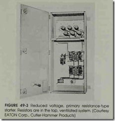
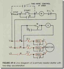
Figure 49-3 and 49-4 illustrate an automatic, primary resistor-type, reduced voltage starter. Figure 49-4 shows the starter with two-point ac celeration connected to a three-phase, squirrel cage induction motor.
When the start button is pressed, a complete circuit is established from Ll through the stop button, start button, coil M, and the overload re lay contacts to L2. When coil (M) is energized, the main power contacts (M) and the control cir cuit maintaining contact (M) are closed. The mo tor is energized through the overload heaters and the starting resistors. Because the resistors arc connected in series with the motor terminals, a voltage drop occurs in the resistors and the motor starts on reduced voltage.
As the motor accelerates, the voltage drop across the resistors decreases gradually because of a reduction in the starting current. At.the same time, the motor terminal voltage increases.
After a predetermined acceleration time, delay contact M closes the circuit to contactor coil S. Coil S, in turn, closes contacts S, the resistances are shunted out, and the motor is connected across the full line voltage.
Note that the stop button controls coil M di rectly. When the main power contacts M open, coilS drops out. After coil M is energized, a pneu matic timing unit attached to starter unit M re tards the closing of time contact M. This scheme uses starter M for a dual purpose and eliminates one coil, a timing relay. Additional control contact
(S) connected parallel to the on-delay contact (M) provides additional electrical security to insure coil S normally open is maintained.
For maximum operating efficiency, push but tons or other pilot devices are usually mounted on the driven machinery within easy reach of the op erator. The starter is located near the motor to keep the heavy power circuit wiring as short as possible. Only two or three small connecting wires are necessary between the starter and pilot device .
A motor can be operated from any of several re mote locations if a number of push buttons or pilot switches are used with one magnetic starter, such as on a conveyor system.
Ac primary resistor starters are available for use on single-phase and three-phase reversing op erations. They are also available with multiple points of acceleration.
Four-point Resistor Starter
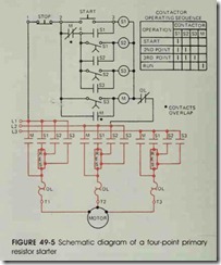
The elementary diagram in figure 49-5 illus trates a four-point resistor starter. Operating the start button energizes contactor S1, connecting the motor to the line. The total resistance is in each line. The mechanically operated timer S1 closes to energize contactor S2. The closing of contacts S2 shunts out a portion of the starting resistor. The mechanically operated timer S2 closes to energize contactor S3. The closing of contacts S3 shunts out additional resistance in the resistor bank. The timer S3 closes to energize contactor M. The clos ing of contacts M connects the motor at full volt
age. An electrical interlock on M then opens to drop out contactors Sl, S2, and S3. The rotor may not start turning until the second or third point, but reduced voltage will have been accomplished.
The timers or timing relays used are of the preset time type such as pneumatic, dashpot or solid-state timers. Compensating-type current re lays are also used.
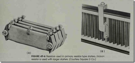
Figure 49-6 shows two types of resistor banks used to start small motors. The resistors (shown in A of figure 49-6) consist of resistance wire wound around porcelain bases and imbedded in refractory cement. The other resistor (B of figure 49-6) has a ribbon-type construction and is used on larger mo tor starters. This type of resistor consists of an al loy ribbon formed in a zig-zag shape. The formed
ribbon is supported between porcelain blocks which have recesses for each bend of the ribbon. The ribbons are not stressed and do not have a reduced cross section, since they are bent on the flat and not on the edge. Any number of units can be combined vertically or horizontally, in series or in parallel.
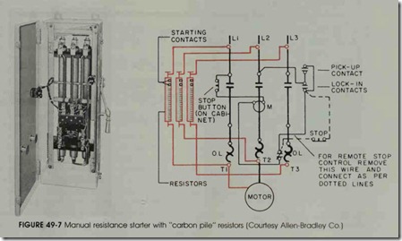
Some starters have graphite compression disk resistors and are used for starting polyphase squir rel cage motors, figure 49-7.
A primary resistance-type starter has the fol- lowing features:
• simple construction
• low initial cost
• low maintenance
• smooth acceleration in operation
• continuous connection of the motor to the line during the starting period
• a high power factor.
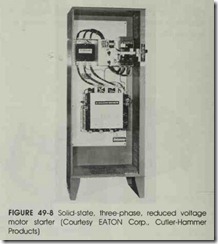
These starters should not be used for starting very heavy loads because of their low starting torque. These starters are said to have a low starting econ omy because the starting resistors dissipate electri cal energy. A solid-state, reduced voltage starter is shown in figure 49-8. Motor and remote control terminal connections are made at a marked termi nal block.
REVIEW QUESTIONS
terminal connections are made at a marked termi nal block.
1. What is the purpose of inserting resistance in the stator circuit during starting?
2. Why is the power not interrupted when the motor makes the transition from start to run?
3. If the starter is to function properly and a timing relay is used, where must the coil of the relay be connected?
4. How many additional steps of acceleration be added?
5. What is meant by the low or poor starting economy of a primary resistor starter?
6. How does this starter provide smooth acceleration and a gradual increase of torque?
