Sensing Devices
Motor control circuits depend on sensing devices to determine what conditions are occurring. They act very much like the senses of the body. The brain is the
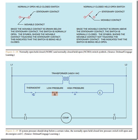
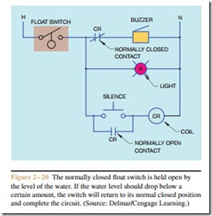
control center of the body. It depends on input information such as sight, touch, smell, and hearing to determine what is happening around it. Control systems are very similar in that they depend on such devices as temperature switches, float switches, limit switches, flow switches, and so on to know the conditions that exist in the circuit. These sensing devices will be covered in greater detail later in the text. The four basic types of switches are used in conjunction with other symbols to represent some of these different kinds of sensing switches.
Limit Switches
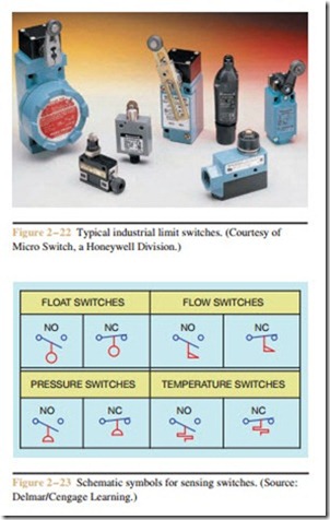
Limit switches are drawn by adding a wedge to one of the four basic switches, Figure 2 – 21. The wedge represents the bumper arm. Common industrial limit switches are shown in Figure 2 – 22.
The symbol for a float switch illustrates a ball float. It is drawn by adding a circle to a line, Figure 2 – 23. The flag symbol of the flow switch represents the paddle that senses movement. The flow switch symbol is used for both liquid and air flow switches. The symbol for a pressure switch is a half circle connected to a line. The flat part of the semicircle represents a diaphragm. The symbol for a temperature switch represents a bimetal helix. The helix will contract and expand with a change of tem- perature. It should be noted that any of these symbols can be used with any of the four basic switches.
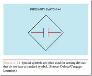
There are many other types of sensing switches that do not have a standard symbol. Some of these
Timed Contacts
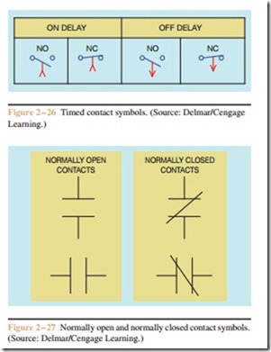
Timed contacts are either normally open or nor- mally closed. They are not drawn as normally open held closed or normally closed held open. There are two basic types of timers, on delay and off delay. Timed contact symbols use an arrow to point in the di- rection that the contact will move at the end of the time cycle. Timers will be discussed in detail in a later chap- ter. Standard timed contact symbols are shown in Figure 2 – 26.
Contact Symbols
Another very common symbol used on control schematics is the contact symbol. The symbol is two parallel lines connected by wires (Figure 2 – 27). The normally open contacts are drawn to represent an open con- nection. The normally closed contact symbol is the same as the normally open symbol with the exception that a diagonal line is drawn through the contacts. The diagonal line indicates that a complete current path exists.
Other Symbols
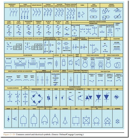
Not only are there NEMA standard symbols for coils and contacts; there are also symbols for trans- formers, motors, capacitors, and special types of switches. A chart showing both common control and electrical symbols is shown in Figure 2 – 28.
