Groups of motors may be supplied by a single feeder. An example would be a feeder from the main service in a barn to the motor control center in a feed room. The feeder wires are required to have a minimum rating equal to the sum of the full load current of all motors supplied, plus 25% of the full load current of the largest motor, NEC Section 430 24. Consider the following example with single phase, 230 V motors:
Silo unloader-5 hp, 28 A
Silo unloader-3 hp, 17 A
Conveyer-! hp, 8 A
Bunk Feeder-2 hp, 12 A
The minimum size wire must have an ampere rating of 72 A
28 + 17 + 8 + 12 + (0.25 X 28) = 72 A
Using copper THWN, the minimum size is No.4 AWG.
Next, the disconnect must be selected for the motor feeder. The disconnect for a feeder serving a group of motors shall have a horsepower rating not less than the sum of the horsepower ratings of the motors served, NEC Section 430 112. For the example, a fusible disconnect switch must have a horsepower rating not less than 5 + 3 + 1 + 2 = 11 hp. The disconnect to be chosen would probably be rated at 15 hp.
If a circuit breaker serves as the disconnect, it must have a current rating not less than 115% of the sum of the full load currents of all the motors served, NEC Section 430 JJO(c)(2). For the example, this would be 75 A.
1.15 X (28 + 17 + 8 + 12) = 1.15 X 65 = 75 A
The minimum size standard circuit breaker would be 80 A
Typically, feeders serving groups of motors will be sized large enough to provide for future expansion. Therefore, the previous calculations serve only as a guide. To make sure that the feeder is adequate for present and future needs, th~ feeder in the example would not be sized for the minimum, but rather for at least 100 A. The wire size could possibly be either No. 3 AWG copper THW or No. 1 AWG THW aluminum. The overcurrent protection would then be sized according to the ampere rating of the feeder, NEC Section 430 62(b)
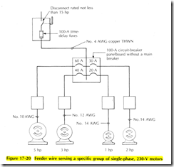
The short circuit protection for a feeder supplying a specific fixed motor load can be sized according to the rules of NEC Section 430 62(a). This only applies to a fixed motor load that will not be changed in the future. Consider the previous example, assuming that circuit breakers serve as the disconnect and short circuit protection for each motor. A fusible disconnect switch will serve as the short circuit protection for the feeder. Figure 17 20 shows the sizes of wire and overcurrent protection for each circuit.
The maximum rating of short circuit protection for the feeder is determined by taking the maximum size motor branch circuit short circuit device and adding to it the full load current of all other motors served. The largest branch circuit protection for the example is a 60 A circuit breaker for the 5 hp motor. Add to this 60 A the full load currents for the 3 hp, 2 hp and 1 hp motors. The fuse size is 100 A maximum.
60 + 17 + 12 + 8 = 97 A
It must be remembered that the feeder overcurrent device is permitted to exceed the ampere rating of the feeder only when the feeder is supplying a specific motor load. The panelboard is often used to serve other loads; therefore, the feeder then must be protected at its ampacity. For the example, a No. 3 AWG copper wire instead of a No. 4 should be chosen
For group motor installations, dual element, timedelay fuses for each motor may be sized at 125% of the motor full load current rating. This provides motor branch circuit protection, as well as running overload protection
The main feeder dual element, time delay fuse may generally be sized at llf2 times the ampere rating of the largest motor of the group, plus the full load current rating of the other motors of the group
(1.5 X 28) + 17 + 8 + 12 = 79 A
(Use 80-A fuses.)
This fuse size would be a minimum.
FEEDER TAPS
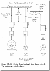
A common practice is to tap motor branch circuits directly from a motor feeder. This is permitted as long as the branch circuit wire is terminated at an overcurrent device sized properly for the circuit, NEC Section 430 28. The branch circuit wire size may be smaller than the feeder wire size. If the tap wire from the feeder to the overcurrent device is not more than 10 ft (3.05 m), and is enclosed in raceway, the branch circuit wire may be as small as necessary to serve the motor load. However, if the tap is more than 10 ft (3. 05 m) but not more than 25 ft (7 .62 m) in length, the branch circuit wire must have an ampere rating at least one third the rating of the feeder conductors.
Consider the example of a No. 4 AWG copper THW feeder wire supplying the three motors of Figure 17 21. The tap wire from the feeder to the fusible disconnect for the % hp and 10 hp, 230 V, single phase motors is not required to be a minimum size because the tap is not more than 10ft (3.05 m) long. However, the ll/2 hp motor tap is more than 10ft (3.05 m) long; therefore, it must have an ampere rating not less than one third that of the feeder wire, or a minimum rating of 28 A. If the wires are copper THW, then the minimum size is No. 10 AWG. If the tap had not been more than 10 ft (3 .05 m) long, then the ll/2 hp motor circuit.could have been wired with No. 14 AWG THW copper wire.
MOTOR CONTROL CIRCUIT
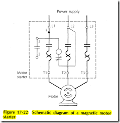
A magnetic motor starter is operated with an electric solenoid coil. A diagram of the power flow to the motor and the control circuit is included with each magnetic motor starter
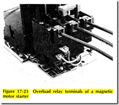
A typical diagram is shown in Figure 17 22. The heavy lines show the power flow to the motor. The narrow lines belong to the control circuit which is prewired by the manufacturer. The holding contact or interlock is the set of contacts between terminals 2 and 3. These contacts close at the same time the main contacts close. The control wire goes from terminal 3 to the coil which closes the contacts, then from the coil through a normally closed overload relay contact. Some motor starters have as many as three of these contacts in series. If the motor overloads, the thermal units will heat up and trip open this overload relay contact, breaking the control circuit and deenergizing the coil. This opens the motor circuit. From the normally closed overload relay contact, the control circuit wire goes to terminal L2. The terminals of the overload relay are shown in Figure 17 23
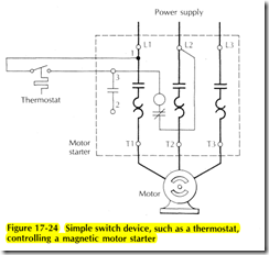
Consider the situation where a simple switching device, such as a thermostat, is used to control the motor, Figure 17 24. When the thermostat closes, it must complete the circuit to energize the motor starter coil. Power is obtained from terminal 1, which is located next to terminal Ll. The other side of the thermostat is connected to terminal 3. When the thermostat closes, electrical current flows from terminal 1 through the thermostat to the coil. From the coil, current flows through the overload relay contact to terminal L2. When the thermostat opens, the circuit is broken and the main contacts open. Only two wires are required when a simple switch device is used to control the motor starter; terminal 2 is not used.
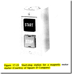
A start stop station (also called a push button station) is another common device used to control a motor. The start and stop push buttons are momentary contacts. They immediately return to their original position after they have been pressed. Figure 17 25 shows a momentary contact push button station
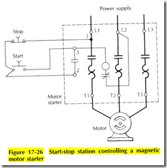
A start stop motor control circuit is shown in Figure 17 26. This requires a 3 wire control circuit. Current can flow from terminal 1 through the normally closed stop button. As soon as the start button is depressed, current flows to terminal 3 and then through the coil to complete the circuit. The main contacts and the holding contact between terminals 2 and 3 are now closed. When the start button is released the start contact opens, but current now flows from terminal 2 to terminal 3 through the holding contact, keeping the coil energized and the contacts closed. Now the only way to stop the motor is to press the stop button or open the overload relay. Diagrams for wiring common motor control circuits are contained inside the motor starter. It is a good idea to put numbers on the control circuit wires to help keep them identified. Figure 17 27 shows the start stop station wires connected to the motor starter. Compare Figure 17 27 with the diagram of Figure 17 26
The diagram of Figure 17 26 is a schematic control wiring diagram for a motor control circuit. It is a little difficult to visualize the operation of the complete control circuit. Examine Figure 17 28 where two separate start stop stations are wired independently to operate the motor. The schematic diagram can be confusing. A type of diagram which helps to visualize easily the components and operation of a control circuit is called a ladder diagram. The entire control circuit is drawn horizontally across the diagram between the two power wires L 1 and L2
Figure 17 29 is a ladder diagram for the start stop control circuit of Figure 17 26. The flow of current can be traced easily from Ll to L2 through each component. Figure 17 30 is a ladder type control diagram of the two start stop stations of Figure 17 28. Stop buttons are wired in series so that any one of them can break the circuit. The start buttons must be wired in parallel so that any one of them can energize the coil. The holding contact is always wired in parallel with the start buttons·
