Hole Nozzles
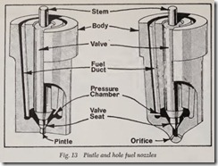
The hole nozzles have no pintle but are basically similar in construction to the pintle type. They have one or more drilled round passages through the tip of the nozzle body beneath the valve seat, Fig. 13. The spray from each orifice is relatively dense and compact, and the general spray pattern is determined by the number and arrangement of the holes. As many as 18 spray holes are provided in the larger nozzles, and the diameter of these drilled orifices may be as small as 0.006 inch. The spray pattern may or may not be symmetrical, de pending on the engine combustion chamber design and fuel distribution requirements.
The size of the hole determines the degree of atomization attained. The smaller the hole the greater the atomization, but if the hole is too small, it will be impossible to get enough fuel into the chamber during the short time allowed for injection. If the hole is too large, there will be an overrich mixture near the nozzle tip and mixture will become leaner as the distance increases from nozzle tip. Multiple-hole nozzles overcome this difficulty, because the holes can be drilled small enough to provide proper atomization and a suf ficient number can be provided to allow the proper amount of fuel to enter during the injection period.
Nozzle Holders
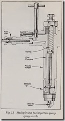
The nozzle holder holds the spray nozzle in its correct position in the engine cylinder, provides a means of conducting fuel oil to the nozzle, and conducts heat away from the nozzle. The holder also contains the necessary spring and a means of pressure adjustment to provide proper action of the nozzle valve, Fig. 12. The body has drilled passages for conducting the fuel from the inlet connection to the nozzle, and its lower end is pro vided with an accurately ground and lapped sur face which m::.kes a leakproof and pressure-tight seal with the corresponding lapped surface at the upper end of the nozzle. The nozzle is secured by means of the cap nut, Fig. 12. At its upper end, the nozzle valve has an extension of reduced di ameter (referred to as the stem) which makes contact with the lower end of the spring-loaded spindle. Adjustment of nozzle-valve opening pres sure is accomplished by means of the spring pres sure-adjusting screw. The adjustment in other types of holders, which are not illustrated, is ac complished by means bf spacers between the top of the spring and the upper spring seat.
WOBBLE-PLATE PUMP SYSTEM
The major difference between the wobble-plate pump system and the injection system previously described, is in the injection-pump unit itself. In the wobble-plate pump, all the pump plungers are actuated by a wobble plate instead of the cus tomary camshaft having an individual cam for each pump plunger. Also, the metering of the fuel is accomplished by a single axially located rotary valve in the wobble plate unit, whereas the rotary movement of the individual plungers controls the amount of fuel in the multiple-unit injection-pump system.
Wobble Plate Pump Principles
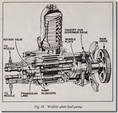
A plate is mounted at an angle on a shaft so that, as the shaft rotates, the plate also rotates and any particular spot on the plate will not only ro tate but will also move laterally, Fig. 15. The pump derives its name from the fact that the plate appears to wobble back and forth as it rotates. The end of a push rod is placed in a guide plate which lays against the wobble plate. The push rod is held in a bore in the pump body so that it can move only in a direction parallel to the wobble plate shaft. The rotation of the wobble plate then causes the guide plate to wobble, thus moving the push rod back and forth. The push rod is con nected to a pump plunger, Fig. 16, so that the movement to the left ach1ates the pump on its de livery stroke and a spring returns it on the suction stroke. The injection pump unit contains one pumping plunger for each engine cylinder. Half the number of plungers are always moving to the right on their filling stroke, the other half are mov ing to the left on the delivery or injection stroke.
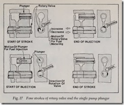
The rotary metering valve is driven by the same shaft that drives the wobble plate. The rotary valve consists of a lapped cylindrical shaft closely fitted in a barrel to prevent fuel from escaping at its ends. Fuel is admitted to the barrel at the cen ter of the valve, which contains a spool-like reduc tion in diameter. This reduction in diameter acts as a fuel reservoir. The recess portion of the valve is in the shape of a band broken by a triangular land of the same diameter as the ends of the valve, Fig. 17. A separate port leads from the re cess to the end of each plunger bore. Through this port the plunger cavity is supplied with fuel. The angular relation of the valve and the wobble plate is such that the valve land will cover each port at the time the respective plunger is at approximately its maximum speed of travel in the direction of dis charge. Prior to port closing and after port open ing (caused by the movement of the triangular land across the port), fuel displaced by the plung er in its pressure stroke flows back through the port into the recess. The fuel trapped in the plunger cavity when the port is closed is forced through a check valve into the high-pressure lines and then to the spray nozzle.
To obtain zero delivery, the valve is moved to a position where the ports are never closed by the land, Fig. 16. The movement of the plungers then merely causes fuel to move in and out through the ports without building up a pressure sufficient to open the delivery valves and cause injection. To cause the pump to deliver fuel, the valve is moved so that, during rotation, the triangular-shaped land closes the port when the plunger is moving in the discharge direction. Further endwise movement of the valve causes a wider portion of the land to pass across the ports, thus, increasing the duratio and the quantity of fuel injected. Each port IS closed for exactly the same duration of plunger travel and therefore exactly the same quantity of fuel is delivered to each of the engine cylinders.
DISTRIBUTOR- TYPE SYSTEM
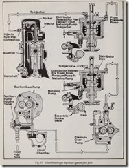
The distributor injection system used in auto motive diesel engines is classed as a low-pressure system in that pumping, metering, and distribution operations take place at a relative low pressure. The high pressure required for injection is built up in the injector at each cylinder, Fig. 18. A uctio gear pump lifts fuel from the tank and dehvers It to the float chamber, from which a second gear pump delivers it, at low pressure, to the distribu tor. Fuel passes through the distributo.r t.o the metering pump, then through the. IS r butor again, and then to the injector where It IS InJected into the cylinder.
Distributor
The distributor consists of a rotating disk and a stationary cover to which are connected fuel lines running to individual injectors. The disk and cover have a series of holes, which, when properly aligned, form passages from the fuel supply pump to the metering pump. This occurs when the me tering plunger moves down on its suction stroke and thus permits the barrel to fill with oil. The disk continues to rotate and lines up with the cor rect discharge hole in the cover just as the meter ing plunger rises by action of the main fue_Jump cam. This forces the fuel into the proper InJector line.
Metering Units
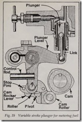
The metering pump is a closely fitted recipro cating type pump, obtaining its motion through a link from the plunger lever. The plunger lever is operated by a vertical lever controlled in tum by an eccentric rocker lever running direct_! off a cam on the fuel pump main shaft. The position of the vertical lever in the eccentric part of the rocker lever determines the travel of the plunger lever and therefore the travel of the metering plunger, Fig. 19. As the metering plunger starts up’;a d on its controlled stroke, it pushes fuel to the InJector through passages formed by th rotating distri u tor disk. The stroke of the metermg plunger, whiCh determines the amount of fuel going to each in jector, is varied by changing the position of the vertical lever between the stop pins in the cam rocker lever. When the roller is against the inside stop pin, the vertical lever and the metering plunger are at the end of their travel consequently no fuel is being delivered to the engine. If the vertical lever is moved over to the outside pin, the stroke of the metering plunger is sufficient to de liver enough fuel to the engine for full speed and load.
Injector
The injector consists of a forged body with a properly fitted plunger, Fig. 20. This plunger is forced down against spring action by a rocker arm actuated by push rods from the engine camshaft. Mounted on the end of the body is a cup which contains the nozzle tip. On the intake stroke of the engine, the fuel metering pump forces a charge of fuel of the exact amount for the load and speed of the engine into this cup. The operation of the metering pump requires that the fuel line and passage leading to the cup be filled with fuel, Fig.21. It naturally follows that any fuel added at the fuel metering pump end will push the same amount of fuel into the injector cup. The fuel lies in the cup during the compression stroke of the engine, and the compressed air is forced through the small spray holes in the cup. The fuel oil in the tip of the cup is exposed to the intense heat and blasting of tl1e compression, and, thus, is pre heated and broken up, Fig. 21. A few degrees before top center, the plunger is forced down and the preheated fuel charge is driven out or injected into the cylinder, Fig. 21; now the plunger ends its stroke. A small check valve is located in the lower end of the fuel passage in the injector body. This check valve prevents the compression pressures from blowing the fuel back and filling the lines with air.
UNIT INJECTION SYSTEM
The unit injection system consists of injectors, fuel supply pump, fuel oil filters, and the fuel oil manifolds. Fuel is drawn from the supply tank through the primary :filter by the fuel supply pump. From the pump, fuel is forced through the secondary filter and to the fuel intake manifold which supplies the injectors. Surplus fuel, flowing through the injectors, is returned through the fuel outlet manifold to the supply tank.
Injector Mounting
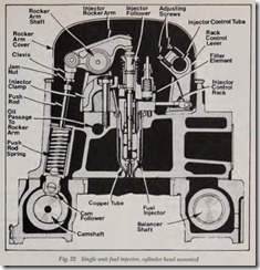
Unit injectors, Fig. 22, combine the injection pump, the fuel valves, and the nozzle in a single housing to elimin ate the high-pressure lines. These units provide a complete and independent injec tion system for each cylinder and are mounted in the cylinder head, with their spray tips slightly .below the top of the inside surface of the combustion chambers. A clamp, bolted to the cylinder head and fitting into a machined recess in each side of the injector body, holds the injector in place in a water-cooled copper tube which passes through the cylinder head. The tapered lower end of the injector seats in the copper tube, forming a tight seal to withstand the high pressures inside the cylinder.
Injector operation
Fuel oil is supplied to the injector, Fig. 23, at a pressure of about 20 psi and enters the body at the top through the filter cap. After passing through the fine-grained filter element in the inlet passage, the fuel oil fills the annular (ring-shaped) supply chamber between the bushing and the spill deflec tor. The plunger moves up and down in this bushing, the bore of which is connected to the fuel supply in the annular chamber by two funnel shaped ports, one on each side at different heights.
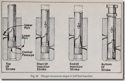
The injector rocker arms, Fig. 22, are actuated through push rods from the engine camshaft. The motion of the injector rocker arm is transmitted to the plunger by the follower, which bears against the return spring. In addition to this reciprocating motion, the plunger can be rotated in operation around its axis by the gear, which is in mesh with the control rack. Each injector control rack is con nected by an easily detachable joint to a lever on a common control tube which, in turn, is linked to the governor and throttle. For metering purposes, a recess with an upper helix and a lower helix or a straight cutoff is machined into the lower end of the plunger. The relation of this upper helix and lower cutoff to the two ports changes with the rotation of the plunger. As the plunger moves downward, the fuel oil in the high-pressure cylin der or bushing is first displaced through the ports back into the supply chamber until the lowest edge of the plunger closes the lower port. The re maining oil is then forced upward through the center passage in the plunger into the recess between the upper helix and the lower cutoff, from which it can flow back into the supply chamber until the helix closes the upper port. The rotation of the plunger, by changing the position of the helix, retards or advances the closing of the ports and the beginning and ending of the injection pe riod. At the same time, it increases or decreases the desired amount of fuel which remains under the plunger for injection into the cylinder.
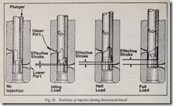
The various plunger positions from “NO-INJEC TION” to “FULL-LOAD” are shown in Fig. 24. With the control rack pulled out completely (noinjection), the upper port is not closed by the helix until after the lower post is uncovered. With the control rack in this position, all the fuel charge is forced back into the supply chamber and no in jection of fuel takes place. With the control rack pushed in completely (full-load), the upper port is closed shortly after the lower port has been covered, thus producing a full effective stroke and maximum injection. From the no-injection position to full-load position (full rack movement), the contour of the helix advances the closing of the ports and the beginning of injection.
The various positions for downward travel of the plunger with the rack in a fixed position, are shown in Fig. 25. On the downward travel of the plunger, the metered amount of fuel is forced through the center passage of the valve assembly, through the check valve, and against the spray-tip valve. When sufficient fuel pressure is built up, the spray-tip valve is forced off its seat and fuel is discharged through several small orifices in the spraytip and atomized in the combustion chamber. The check valve prevents any leakage from the combustion chamber into the fuel system if the spray-tip valve is accidentally held open by a small particle of dirt, allowing the injector to operate until the particle works through the valve.
On the return upward movement of the plunger,the high-pressure cylinder is again filled with oil through the ports. The constant circulation of fresh coal fuel through the injectors, which renews the surplus fuel supply in the chamber, helps to maintain even operating temperature of the in jectors, and also effec;:tively removes all traces of air which might otherwise accumulate in the sys tem. The amount of fuel ‘circulated through the injector is in excess of maximum needs, thus insur ing sufficient fuel for all conditions.
FUEL SUPPLY UNITS
Fuel Supply Pumps
Fuel injection pumps must be supplied with fuel oil under pressure because they have insuf ficient suction ability. Therefore, all injection sys tems require supply pumps to transfer fuel from the supply tanks to the injection pumps. Pumps used for this purpose have a positive suction lift, and their performance is largely independent of any reasonable variations in viscosity, pressure, or temperature of the fuel. The pumps in use today are of the gear, plunger, or vane types. The gear type is similar in operation to the pump used in the gasoline engine lubrication system, covered
elsewhere in this textbook, hence the discussion of supply pumps in this paragraph will be limited to the vane and plunger types.
Vane Type
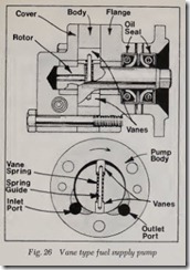
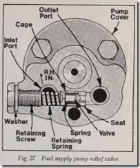
The vane type fuel oil pump, Figs. 26 and 27, has an integral steel rotor and shaft, one end is supported in the pump flange and the other end in the cover; it revolves in the body, the bore of which is eccentric to the rotor. Two sliding vanes are placed 180° apart in slots in the rotor and are pressed against the body bore by springs in the slots. Two oil seals on the pump shaft prevent leakage of fuel or lubricating oil. A drain hole be tween the two seals leads to the atmosphere.
When the shaft is rotated, the vanes pick up fuel at the inlet port and carry it around the body to the outlet side, where the fuel is discharged. Pres sure is produced by the wedging action of the fuel as it is forced toward the outlet port by the vane. A spring-loaded horizontal relief valve is provided in the cover of the pump, connecting the inlet and outlet ports, and opens at a pressure of approxi mately 55 psi. This valve does not normally open, since its purpose is to relieve excessive pump pres sure, if any of the fuel lines or filters become plugged, and build up an extremely high pressure in the pump. When the valve opens, fuel passes from the discharge side (pressure side) to the suction side of the pump, relieving pressure.
Plunger Type
This type of pump, Fig. 28, is usually mounted directly on the housing of the injection pump and is driven by the injection pump camshaft. It is a variable-stroke self-regulating plunger-type pump that will build pressure only up to a predeter mined point.
As the injection pump cam allows the plunger to be forced by its spring toward the camshaft, the suction effect created opens the inlet valve and permits the fuel to enter the plunger spring cham ber. As the cam lobe drives the plunger against its spring, the fuel is forced by the plunger through the outlet valve and around into the chamber created in back of the plunger by its forward movement. As the injection pump cam continues to rotate, it allows the plunger spring (which is now under compression) to press the plunger backward again, forcing the fuel oil behind the plunger out into the fuel line leading to the filters and injection pump. At the same time, the plunger is again creating a suction effect, which allows additional fuel to flow through the inlet valve into the spring chamber. This pumping action continues as long as the fuel is being used by the injection pump, fast enough to keep the supply pressure from rising to the point where it equals the force exerted by the spring on the plunger. The pressure between the supply pump and the injection pump holds the plunger stationary against the spring and away from the rod. This prevents further pumping action until the pressure drops enough to permit the plunger to resume operation. This entire cycle is automatic and con tinues as long as the engine is running.
GOVERNORS
All diesel engines require governors to prevent over-speeding of the engines under light loads. Au tomotive diesel engines also demand control of the idling speed. Any of the installations provides a variable-speed control which, in addition to con trolling minimum and maximum speeds, will main tain any intermediate speed desired by the opera tor. Engine speed in a diesel engine is controlled by the amount of fuel injected; consequently, the injection system is designed to supply the maxi mum amount of fuel which will enable the engine to operate at full load and reach a predetermined maximum speed (rpm). However, if the maximum fuel charge was supplied to the cylinders with the engine operating under “PARTIAL LOAD” or “NO LOAD,” the engine speed would increase beyond the critical range and soon cause a failure. Thus, it can be seen that the governor must control the amount of fuel injected in order to control the engine speed.
Governors may be actuated through the move ment of centrifugal flyweights or by the air-pres sure differential produced by a governor valve and venturi assembly. The centrifugal flyweight type may incorporate a mechanical linkage system to control the injection pump, or it may include a hydraulic system td transmit the action of the weights to the pump. Where the rate of accel eration must be high, the governor-controlling weights must be small to obtain the required speed of response from the governor. These small weights may not exert sufficient force to control the injection equipment; instead, the injection pump will be controlled by a servo piston utilizing pressure from a pump within the governor. The centrifugal weights actuate a valve which controls the amount of oil going to the servo piston.
Mechanical (Centrifugal)
The operation of the mechanical governor is based on the centrifugal force of rotating weights counterbalanced by springs. When the speed of the engine increases, the weights :By outward, pull ing with them suitable linkage to change the set ting of the injection pump control rod. The gov ernor linkage is connected to the injection pump in such a manner that the spring moves the con trol mechanism toward the full-fuel position, and the action of the fly-weights reduces the amount of fuel delivered.
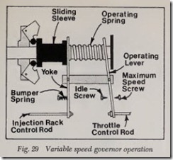
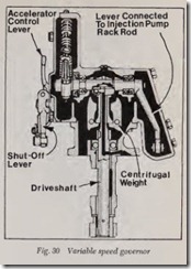
Utilizing a variable speed governor, Figs. 29 and 30, the operator varies the governor spring tension to control the quantity of fuel and does not at any time move the injector control rack directly. The control rack of the injection pump is connected to the yoke of the governor in such a manner that any movement of the yoke will direct ly affect the quantity of fuel injected. The spring tension is controlled by the operating lever, the movement of which is determined by the position of the foot throttle. The travel of the operating lever is limited by the idle and maximum-speed screws. With the weights fully collapsed (engine stopped), the spring moves the sliding sleeve and yoke so the fuel injection pump is in the full-fuel position. When the weights are fully extended, the sliding sleeve and yoke move to the right and de crease the amount of fuel delivered.
If the load on the engine is decreased, the engine tends to accelerate. However, when the en gine accelerates, the governor flyweights move outward as a result of increased centrifugal force. Since the flyweights are in contact with the sliding sleeve assembly, this movement causes a longi tudinal movement of the sleeve to the right. This movement continues until an equilibrium is estab lished between the governor spring force and the centrifugal force exerted by the flyweights. This occurs when the engine returns to the original speed, as determined by the position of the foot throttle and its effect on the governor spring.
If the load on the engine increases, the engine tends to slow down, thereby causing an inward movement of the flyweights. As the weights move inward, resulting in reduced force on the sliding sleeve, the compressed governor spring shifts the sleeve to the left until the spring force and the centrifugal force exerted by the flyweights are again balanced. In this way, the yoke, following the movement of a sliding sleeve, moves the con trol rack of the fuel injection pump toward the more-fuel position thereby returning the engine to the preset speed.
To accelerate the vehicle, depress the foot throt tle, which, in turn, increases the spring tension. This causes the yoke to pivot to the left, thereby increasing the supply of fuel. The flyweights move outward as a result of increased engine speed and prevent the control rack from reaching the full fuel position, unless the foot throttle is fully de pressed. Deceleration is accomplished in the re verse manner . Spring pressure is decreased, the engine slows down, the flyweights move inward, and a balanced condition between the flyweights and the spring is obtained at a lower engine speed.
The adjustable bumper spring prevents rapid oscillations of the control rack at low no-load en gine speeds. The spring contacts the yoke at idling speed and insures steady operation of the gov ernor. The bumper spring also assists in preventing stalling of the engine on sudden deceleration to idle speed, as it prevents the control rack of the injection pump from moving into the full-stop position when this speed change occurs.
Pneumatic
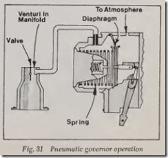
The actuating force for the pneum atic or vac uum-controlled governor is the pressure drop caused by the velocity of air passing through a venturi located in the air intake manifold. The governor, Fig. 31, consists essentially of an atmo spheric-suspended diaphragm connected by link age to the control rack of the fuel injection pump. The chamber on one side of the diaphragm is open to the atmosphere, and the chamber on the other side is sealed and connected to the venturi in the manifold. In addition, there is a spring acting on the sealed side of the chamber, which moves the diaphragm and control rack to the full-fuel posi tion when the engine is not operating and both sides of the diaphragm are at atmospheric pressure.when the engine is running, however, the
pressure in the sealed chamber is reduced below the atmospheric pressure existing in the other chamber. The amount of pressure reduction de pends on the position of the governor valve and the speed of the engine. It is this pressure dif ferential that positions the diaphragm and conse quently, the control rack. The governor valve is controlled by a lever which is connected by suit able linkage to the foot throttle. There is no actual connection between the foot throttle and the gov ernor or fuel injection pump.
If the engine is operating under load and the speed (rpm) is below governed speed , the velocity of air passing through the venturi is comparatively low and only a slight pressure differential is present. The spring moves the diaphragm and control rack toward the full-fuel position and the engine speed approaches that of governed speed. The same principle prevents the engine from over speeding at light loads. As the engine speeds up, the velocity of air through the venturi increases, with the result that the pressure differential at the diaphragm is increased. This differential is sufficient to overcome the spring force and to cause the diaphragm and control rack to move toward the STOP position. When the engine is operating at governed speed with the valve wide open, the pressure differential is just s!ightly below at ?f the spring force, and the d1aphragm remams m the full-delivery position.
For any position of the governor valve between idling and full load of the engine, the diaphragm finds its relative position. Since any movement of the diaphragm is also transmitted to the control rack, the amount of fuel delivery is definitely con trolled at all engine speeds. As the pressure drop between the chambers is increased, the diaphragm is moved in the direction calling for reduced fuel delivery. As the pressure drop is decreased, the spring can move the control rack in the direction of greater fuel delivery. Therefore, in order to in crease the speed of the engine, the governor valve is opened; to decrease the engine speed, the valve is closed.
FUEL FILTERS
Thorough and careful filtration is especially necessa ry to keep diesel engines efficient. Dies l fuels are more viscous than gasoline. They contam more gums and more abrasive particles, which may cause premature wear of e injection .equip ment. The abrasives may cons1st of matenal dif ficult to eliminate during the process of relining, or they may enter the fuel tank through careless refueling. Whatever the source, it is imperative that means be provided to protect the system from these abrasives.
Most diesel engine designs include two filters in the fuel supply system to ,protect the closely fitted parts in the pumps and nozzles. The primary (coarser) filter is usually located between the supply tank and the fuel supply pump. The sec ondary (finer) filter is found between th . fuel supply pump and the injection pump. Additional filtering elements are frequently installed between the injection pump and the nozzle.
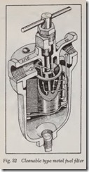
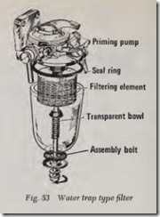
Diesel fuel oil filters are referred to as full-flow filters, since all the fuel must pass throug the filters before reaching the injection pumps. Filters must be inspected regularly and cleaned or re placed if maximum efficiency is to be maintained. Some filter elements are cleanable, Fig. 32, but most filtering elements must be replaced when they becom e dirty. Since water is an extremely dangerous polutant of diesel fuel, water tr p filte s are used very extensively, Fig. 33. A diesel 01l filter usually incorporates an air vent to release any air which might accumulate in the filter dur ing operation.
![Fig. 15 Wobble plate pump operation_thumb[1] Fig. 15 Wobble plate pump operation_thumb[1]](http://machineryequipmentonline.com/electric-equipment/wp-content/uploads/2020/06/Fig.-15-Wobble-plate-pump-operation_thumb1_thumb.jpg)
![Fig. 20Distributor type fuel system in;ector_thumb[1] Fig. 20Distributor type fuel system in;ector_thumb[1]](http://machineryequipmentonline.com/electric-equipment/wp-content/uploads/2020/06/Fig.-20Distributor-type-fuel-system-inector_thumb1_thumb.jpg)
![Fig. 21 Four fuel infection cycle stages_thumb[1] Fig. 21 Four fuel infection cycle stages_thumb[1]](http://machineryequipmentonline.com/electric-equipment/wp-content/uploads/2020/06/Fig.-21-Four-fuel-infection-cycle-stages_thumb1_thumb.jpg)
![Fig. 23 Fuel injector, typical_thumb[1] Fig. 23 Fuel injector, typical_thumb[1]](http://machineryequipmentonline.com/electric-equipment/wp-content/uploads/2020/06/Fig.-23-Fuel-injector-typical_thumb1_thumb.jpg)
![Fig. 28 Plunger type fuel supply pump_thumb[1] Fig. 28 Plunger type fuel supply pump_thumb[1]](http://machineryequipmentonline.com/electric-equipment/wp-content/uploads/2020/06/Fig.-28-Plunger-type-fuel-supply-pump_thumb1_thumb.jpg)
