Bosch D-Jetronic and L-Jetronic (ECGI)
Both of these Electronically Controlled Gasoline Injection systems ( ECGI) are almost identical ex cept for one feature. On the earlier D-Jetronic system, fuel delivery was regulated by an intake manifold pressure sensor. On the newest L-Jetronic system, the fuel delivery is regulated by the amount of air flow into the engine.
The air-flow sensor has several advantages over the intake-manifold pressure sensor used with Bosch D-Jetronic system: all changes within the engine (wear, carbon deposits, valve lash, etc.) are automatically compensated for because they all affect air flow; exhaust gas can be recirculated without any special provisions; idle stability is better; and both acceleration enrichment and alti tude compensation are virtually automatic.
Naturally, all the normal advantages of fuel in jection over carburetion accompany this system. This includes more power output because long tuned intake passages are possible with no fuel
separation, and no heat need be added to vaporize the fuel. Lower emissions are easy to achieve be cause of the tight control over both airjfuel ratio and cylinder-to-cylinder distribution.
Ten years of electronic fuel-injection production has brought many improvements to the L-Jetronic Vacuum unit Trigger contact Cam system. Integrated circuits have reduced the num ber of individual electronic components from 300 to 80. Also, detecting elements are now much cheaper to manufacture and significantly more re liable in service. There is tremendous flexibility inherent in any electronic control, so this system will quite handily accept the Lambda probe for three-way catalyst control of exhaust emissions. That alone should buy it a place in many future cars.
There is really only one factor that has limited L-Jetronic’s popularity (it’s currently used only on the BMW 630CSi and 530i, Datsun 810 and 280-Z, and the VW Beetle). It suffers from a stigma, as do all other electronic components: if it can’t be fixed with a wrench, mechanics would rather not know about it.
We will concentrate here on the L-Jetronic, since it is the more commonly used system and because more and more manufacturers will be using this system in the future.
OPERATING PRINCIPLES
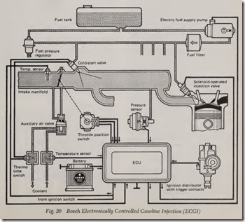
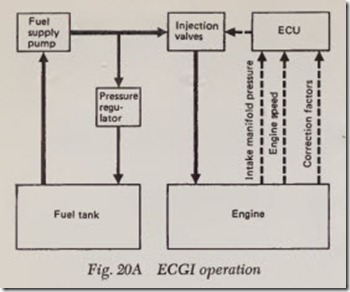
The Bosch Electronic Gasoline Injection System ( ECGI), Figs. 20 and 20A, is controlled by the intake manifold pressure and the engine speed which injects the fuel into the intake manifold about 10-15 em before each cylinder inlet valve. The injected fuel quantity is regulated by con trolling the time during which the solenoid-oper ated injection valves open. Since the orifice area of the injection valves is precisely calibrated and the fuel pressure is held constant, the injected fuel quantity depends solely on the length of time the injecpon valve is open. The system is controlled by the Electronic Control Unit ( ECU), which processes information received from the engine concerning its operating condition and which then transmits electrical pulses to the valves to control the instant and duration of each injection.
Instant of Injection
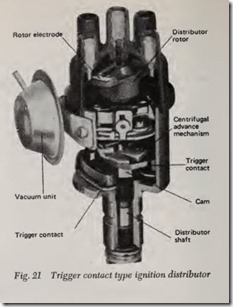
The beginning of the pulse which causes the in jection valve to open is determined by the ignition distributor contacts (trigger contacts), depending on the position of the camshaft. These contacts are located in the distributor under the centrifugal advance mechanism and are activated by a cam on the distributor shaft, Fig. 21. In addition, the ECU receives information on the engine speed from the intervals between the higger pulses (which come from the trigger contacts), and this information is one of the inputs used to calculate the duration of injection.
Duration of Injection
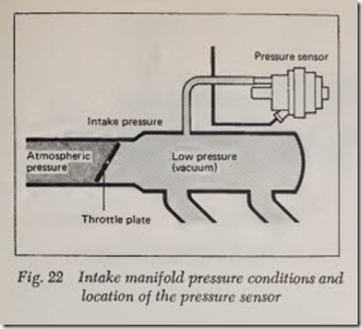
The open time of the injection valves, and there fore the quantity of fuel which is injected, is determined for the most part by two factors: the speed of the engine and the load on it. As men tioned above, information on the engine speed is transmitted to the ECU from the distributor trig ger contacts. The engine load ( pa1t or full load) can be determined from the pressure conditions in the intake manifold, Fig. 22. The pressure prevail ing here at any time is converted into an electrical quantity by the pressure sensor and is also fed to the ECU, Fig. 22. The ECU then commands the injection valves, by means of current pulses, to in ject more or less fuel. In this way the ‘basic fuel quantity” is determined.
In addition to this “basic fuel quantity,” under certain operating conditions an additional definite, precisely metered quantity of fuel must be in jected. These conditions require correction factors covered further on in this chapter.
Components
The system consists essentially of the fuel system, the induction system, and the control system.
Fuel System
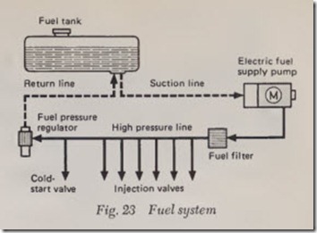
In the fuel sy,stem, a fuel supply pump draws the fuel from the fuel tank and forces it through a filter and through the distribution line and its branches to the solenoid-operated injection valves. The fuel pressure at the valves is held constant by a fuel pressure regulator. Excess fuel flows back pressure-less to the tank. To prevent foreign par ticles from reaching the injection valves there is a fuel filter fitted between them and the pump, Fig. 23. Each cylinder has a solenoid-operated injection valve which opens once for each working cycle (rotation of the camshaft). Depending on engine design, the injection valve is located either in the intake manifold or in the cylinder head. In every case, however, injection takes place into the intake manifold before the inlet valve.
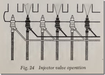
In order to reduce the complexity of the ECU,in 4-cyl. engines two groups of two injection valves each are formed. The valves in a given group are connected electrically in parallel and open simul taneously, Fig. 24. The same applies for 6- and 8-cyl. engines (two groups of three valves each, four groups of two valves each respectively).
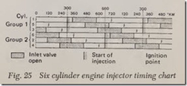
The 6-cyl. engine injection timing chart shows the sequence of start injection, opening of the inlet valve, and ignition point, referred to the crank shaft position in degrees, Fig. 25. The air-fuel mixture is stored for each cylinder before its inlet valve and is drawn into the cylinder when the inlet valve opens. Ignition of the mixture takes place in each cylinder shortly after its inlet valve closes.
Electric Fuel Pump
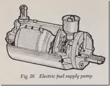
The fuel supply pump in this system is a roller type pump, Fig. 26, driven by a permanent-magnet electric motor. An eccentric rotor mounted on the motor shaft has metal rollers housed in pockets around its circumference which are forced out ward by centrifugal force and which act as seals. In the gaps formed between the rollers the fuel is forced through the pump and into the high pressure line. The pump is designed as a so-called “wet pump,” which means that the electric motor is filled with fuel. There is no danger of explosion, however, because the pump housing never con tains an explosive mixture. The pump delivers fuel at about 21 and 31 gallons/hour (about 80 and 120 liters/hour).
When the ignition is turned on at the ignition switch, the pump runs for only about one second and then stops. Only after the engine has started is the pump switched on again by the ECU through a relay. This protective system (called flooding protection) prevents flooding of ·the par ticular cylinder with fuel, in event of a possible defective injection valve when the ignition has been switched on.
Pressure Regulator
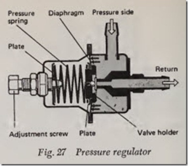
The fuel pressure is held at a constant value by the pressure regulator. This regulator consists of a metal housing in which a spring-loaded dia phragm frees the opening to an overflow duct if the pressure setting is exceeded. The pressure is adjusted by changing the pretension of the dia phragm spring, Fig. 27.
Solenoid-Operated Injection Valve
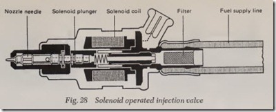
The solenoid-operated injection valve, Fig. 28, consists essentially of a valve body and the nozzle needle to which the solenoid plunger is attached. The movable plunger is attached rigidly to the nozzle needle, which is pressed against the valve seat in the nozzle body by a helical spring. The solenoid coil is mounted in the rear section of the valve body, with the guide for the nozzle needle in the front section.
The current pulses received from the ECU build up a magnetic field in the coil. As a result, the plunger is attracted and lifts the nozzle needle from its seat. This opens the path for the pres surized fuel. Valve lift is about 0.15 mm, and lift period about 1/1000 second. Depending on the amount of fuel required to be injected, the injec tion valve is held open from 2/1000 to 10/100 seconds.
Induction System
The volume of air required for combustion of the fuel is drawn through the air cleaner and past the air throttle valve into the intake manifold. From here individual intake tubes of equal length branch out to each cylinder. This design ensures that absolutely equal amounts of air are fed to the individual cylinders. Generation of the air-fuel mixture starts with the injection of the fuel charge into the charge of air which has been drawn into the cylinder by the reciprocating movement of the piston. .
In the intake manifold, atmospheric pressure prevails in front of the throttle pla-te (air cleaner side), whereas after the throttle plate there is a lower pressure which is constantly changing de pending on the throttle plate position, Fig. 22. This changing absolute pressure in the manifold is used as a parameter for determining the most important item of information, the engine load.
Pressure Sensor with Full-Load Enrichment
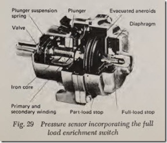
The pressure in the intake manifold is provided by the pressure sensor, Fig. 29. For this reason we also refer to this sensor as an “intake manifold pressure sensor,” Fig. 22.
The pressure sensor measuring system is in stalled in a pressure die-cast housing which is con nected to the intake manifold of the engine by a hose. The pressure sensor contains two evacuated aneroids which shift the position of a plunger in side a coil. As the load increases, that is, as the absolute pressure in the intake manifold increases, the aneroids are compressed, moving the plunger more deeply into the iron core of the coil, thus increasing the inductance of the coil. This results in a longer opening pulse to the injection valve and thus a larger amount of fuel is injected.
When the air throttle valve is closed the intake manifold pressure is low, the aneroids are less compressed, and they move the plunger out of the iron core. This lowers the inductance of the coil,
and as a result, the opening pulse is shorter and the valves inject a smaller amount of fuel.
The inductive data transmitter (the coil) in the pressure sensor is connected to an electronic timer in the ECU which determines the duration of the opening pulse to the injection valve. During the pulse the valve is open. In this way the intake manifold pressure is converted directly into a corresponding pulse duration (injection duration).
It should basically be kept in mind that the start of injection is activated by the trigger contacts in the distributor, while the duration of injection, and thus the injected fuel quantity, is determined by the pressure sensor through the electronic timer in the ECU.
