HYDRAULIC LASH ADJUSTERS
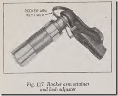
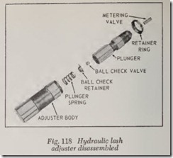
The Pontiac Tempest overhead camshaft engine uses this device to maintain zero lash automati cally. Located in the cylinder head, it serves as the fulcrum of the rocker arm and also locates the rocker arm accurately with the camshaft. A spher ical radius on the lash adjuster, which mates with a spherical socket on the rocker arm, absorbs the transverse thrust due to friction between the cam lobe and rocker ann. The lash adjuster is attached to the rocker arm by means of a retainer, Fig. 117. Operation and service of the adjuster is similar to that of a hydraulic valve lifter used in a conven tional push rod engine. Fig. 118 shows the ad juster disassembled.
VALVE ROTATORS
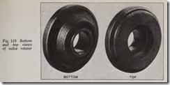
In its 1970 models, Oldsmobile adopted valve rotators, Fig. 119. These are devices fitted to the valve stem which force the valve to rotate about three degrees each time it is lifted off its seat. Purpose of the device is to keep the valve seat clean so that the valve can close properly every time the cam permits it to drop on its seat. It prevents the formation of deposits on the valve face and seat, improves valve cooling because of the better contact with the seat, and greatly lengthens the life of the valve. Valve rotators have been used for many years on truck engines, but this is the first use in passenger cars.
MODIFYING VALVE GEAR FOR HIGH PERFORMANCE
Many of the operations required to modify an engine for high performance are no different from those used in normal engine service. These in clude checking valve seat face runou t, valve stem clearance, reaming valve guides, etc. Other opera tions that are of particular importance in modify ing for high performance include:
Refinishing Valve Seats
Refinishing the valve seat should be closely coordinated with the refacing of th e valve so that the finished seat and valve face will be concentric and the specified interference angle will be main tained. This is important so that the valve and seat will have a compression-tight fit. Be sure that the refacer grinding wheels are properly dressed. For high performance applications, some specifications call for an intake valve seat and face angle of 30° and exhaust valve seat and face angle of 45°. When grinding valve seats remove only enough stock to clean up pits and grooves or correct the valve seat runout. On the valve seats of most engines, a 60° angle grinding wheel can be used to remove stock from the bottom of the seat (raise the seats) and a 30° angle wheel can be used to remove stock from th top of the seats (lower the seats).
On stock.engines, the finished valve seat should contact the approximate center of the valve face. However, for high performance engines, valve seats should contact the valve face as far out on
th e edge of th e valve as possible. This provides a larger eff ective valve opening and improves en gine br eathin g. The point of valve seat and face contact can be found by using machinist blueing. Coat the seat with blueing, set the valve in place and rotate it with light pr essure. The blueing will transf er to the valve face, showing where the contact occurs.
Valve Seat Width
After th e seat has been finished, use a seat width scale or a machinist scale to measure the width. Stock engine seat widths usually run be tween .050″ and .080″. This allows for more effi cient he at transfer during periods when the engine is idlin g or operating at low speeds. For drag strip operating, Ford, as an example, specifies an intake seat width of .035″ and an exhaust seat width of
.050″. It is important to remember that valve seat width is critical. Too wide a seat can collect deposits of carbon; too narrow a seat won’t dissi pate heat fast enough.
Refacing Valves
If the valve face runout is excessive, or if the face is pitted or grooved, the valves should be refaced. Remove only enough stock to correct runout or to clean up the pits and grooves. If the edge of the valve head is less than 1/32″ thick after grinding, replace the valve as it will run too hot. The interference angle of the valve and seat should not be lapped out. Remove all grooves and score marks from the end of the valve stem and chamfer it as necessary. Do not remove more than 10 ” from the end of the stem. The valve stem, from the valve lock groove to the end, must not be shorter than the minimum specified length.
If the valve and/or valve seat has been refaced, it will be necessary to check the clearance be tween the rocker arm pad and the valve stem with the valve gear installed in the engine.
Installing Larger Valves
Using larger valves may or may not improve engine breathing ability. Larger valves run hotter than smaller ones and they are heavier as well. This could mean burned valves or high speed valve float if the proper precautions are not taken. In addition, valve shrouding by the combustion chamber walls may occur.
in many cases, increasing valve size will .neces sitate other modifications such as chamfermg or boring the cylinders and using deflector or dome type pistons to achieve the best result . If lm:ger valves are to be installed, the followmg pomts should be borne in mind:
1. Use a hand-operated reamer to remove large amounts of stock from the valve ports.
2. Measure the face of the new valve and stop reaming when the diameter of the reamed hole equals the smallest diameter of the valve face.
3. It may be necessary to remove some stock from the combustion chamber walls to reduce valve shrouding and improve mixture flow.
4. Check piston-to-valve clearance.
Valve Springs
For best high speed performance, it is impor tant that valve springs be tested and properly installed. A spring testing fixture should be used to measure “full open” pressure and “seated” (fitted dimension) pressure. When checking the inner spring on a dual spring arrangement, re member that the inner spring often rides on a stepped portion of the spring retainer. This must be allowed for by compressing the inner spring more than the outer spring. For example, if the step is 1/16″ thick, the inner spring must be com pressed 1/16″ more than the outer one.
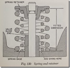
When the spring is at “Full open” pressure, check for coil stacking or coil bind. Coil bind can ruin the valve train. If a .010″ to .012″ feeler will go between each coil, there is no danger of coil stacking. On some high performance cam kits with inner and outer valve springs, it may be necessary to reduce the diameter of the valve guides to permit installation of the inner springs. Also, the outer spring seats may have to be enlarged to accommodate the larger spring diameter. This can be done by using a special counterb oring tool available from most speed shops . Once the -springs are installed, check the fitted dimension . Measur e the spring only, Fig. 120, and do not include th.e thickness of the retainer. If the measurement IS less than that specified, the spring seat will hav e to be counterbored to obtain the correct dimen sion. If the measurement is greater than that specified, use spacer washers under the spring.
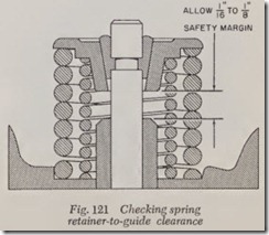
Another important item which should b e checked is spring retainer to valve guid e clear ance, Fig. 121. This is critical when a high lift cam is fitted. Checking should be done with the valve gear assembled and adjusted to specifications. Rotate the engine until the valve is in the full open position. There should be 1/16″ to 38″ cle r ance between the valve guide end and the spring retainer. It may sometimes be neces sary to ma chine the valve guide slightly to obt ain th e proper clearance.
Rocker Arm Geometry
Correct rocker ann geometry will allow longer engine operation at high speeds with little valve guide bore wear. With the valve position ed at 40% to 50% of maximum lift, the rocker arm tip radius should coincide with the center line of th e valve stem. If the rocker arm tip coincides with the center of the valve stem at less than 40% of total lift, the push rod should be shorten ed by the amount of the difference between the two cent er lines. Where the rocker arms are m ounted on a rocker shaft, the rocker arm geometry can be off if the adjusting screw is screwed in to the limit of its travel. A longer pushrod should be used to correct for this condition.
Rocker Arm-to-Stud Clearance
If a high lift cam is installed, exceeding ap proximately .450″, rocker arm-to-stud clearance should be checked on those engines which hl:).ve ball-type rocker arms. There should be .040″ to
.060″ clearance on both sides of the rocker arm when the valve goes through a complete opening and closing cycle. One method of checking for this clearance is to use a piece of solder about 6 in. long and 1/16″ ( .062″) in diameter. Form a hook in the solder so that it will fit betwee n the slot in the rocker arm and the stud. Then turn the engine over until the valve has gone through a complete cycle. If there is sufficient clearance, the rocker arm should not make an impression in th e solder. Check for clearance on both sides of th e stud. If the clearance is not great enough, be careful only to elongate the slot in the arm and n ot widen it.
Timing Gear, Chain, Belt & Camshaft Service
VALVE TIMING
Except Pontiac Tempest OHC Engine
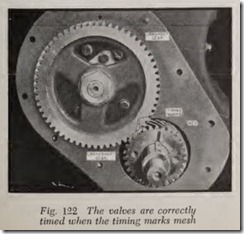
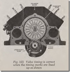
When the camshaft is driven by gears it is the custom to mark the gears in one of two ways, Figs. 122 and 123. In Fig. 122 there are three circular marks on the meshing teeth whereas in Fig. 123 there are two marks which should be lined up as shown.
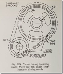
In the case of timing chains and sprockets, there are also two common methods of marking. In Fig. 124 it will be seen that marks on the sprockets should line up with a line drawn between the centers of the crankshaft and the camshaft. In Fig. 125, the correct camshaft setting is determined by the number of links between the two marks on the sprockets.
It is important to note that when meshing a timing chain with its sprockets that the marks should always be on the taut side of the chain. This advice applies to the markings illustrated in Fig. 125 and not to Fig. 124. To determine the taut side, just rememb er that the rotation of the crankshaft sprocket pulls on the chain and thus rotates the camshaft sprocket. Obviously the side of the chain that docs the pulling is the taut side.
The crankshaft gear or sprocket is keyed to the crankshaft and cannot slip unless perchance the key is sheared off-a rare and unlikely possibility. Similarly the camshaft gear or sprocket is firmly and positively attached to the camshaft. It is either keyed to the camshaft or bolted to a hub on the camshaft.
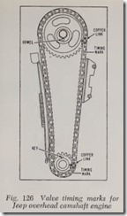
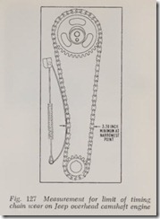
Chain slippage is quite rare on modern cars because the chains are relatively short-the shorter the chain the less it stretches as it wears. A possible exception would seem to be the chain used in the Jeep overhead camshaft engine, Fig.126. However, this is prevented by the tensionerdevice shown. The chain tensioner maintains a constant pressure against the chain to compensate for normal stretch and wear of the chain. When ever the chain case cover is removed for any reason, the chain should be checked for wear as suggested in Fig. 127. If the space between the arrows indicated is less than the minimum, a new chain should be installed. The procedure for in stalling the chain is covered further on in this chapter.
Timing marks are located either on the vibration damper, crankshaft pulley or on the front face of the flywheel and usually the marks apply to No. 1 cylinder. If no marks are found on the vibration damper or pulley look for an inspection hole on the front side of the flywheel housing. Remove the hole cover and then turn the flywheel until the marks on the flywheel appear.
Turn the engine over until the distributor rotor points to the segment eonneeting with the spark plug eable running to the last eylinder. Then rotate the erankshaft slightly by pulling on the fan blades until No. 1 intake valve is just ready to open.
The reference mark on the flywheel housing may be a pointer or may be merely a straight line cut into the flywheel housing. If there is no pointer or mark, it is assumed that the “zero” point is at the eenter of the opening. In the case of vibration dampers or pulleys there is a pointer or an indieating mark on the timing ease eover to indieate thP, “zero” point.
To eheck valve timing, the valve stem-to-tappet clearanee must be known. Note that on ears equipped with hydraulie tappets the elearanee is always zero. On other ears the valve elearanee for eheeking valve timing is often different from the elearanee required for running the engine. In sueh eases the faetories reeommend that No. 1 intake valve, for example, be adjusted to the speeified valve timing elearance. If the faetory reeommends the same elearanee for valve timing as for run ning, the elearanee should be eheeked and if not correet it should be adjusted. Be sure to use the speeified elearanee, as otherwise the valve timing cheek may be in error by five or ten degrees or more.
On engines with hydraulie tappets, th e opening of No. 1 intake valve ean be approximately deter mined by feeling for initial motion in the body of the t appet while the engin e is s!Gwy ro tated to open the valve. The slightest upwar d motion of the tappet indicates the valve opening point.
A more aeeurate method is to mount a dial indicator on the engine. The tip of the gauge should contact the lifter body, not the plunger. Then turn the engine over slowly until the lifter body causes the gauge pointer to move ever so slightly.
If a dial gauge is not available, drain the oil from the hydraulic lifter and then eliminate the clearance between the plunger and the valve stem with feeler stoek. When doing this be sure that the valve is fully closed.
After adjusting No. 1 intake valve, eheek the timing as follows: Remove the distributor eap and turn the engine over until the rotor approaches the distributor segment eonneeted to the spark plug wire running to the last cylinder in the bloek. Then turn the engine slowly by pulling on the fan blades with one hand while the other hand is used to rotate the t ppet on an L-head engine or the push rod on an overhead engine. When the tappet or push rod begins to bind, No. 1 intake valve is ready to open. If valve timing is correct the valve opening mark should be in line with the reference mark or pointer. If the timing is correct within a few degrees, it should be considered satisfactory. But if the timing is wrong by 10 or more degrees, remove the eover and replace the gears or ehain.
To determine how mueh the error of one tooth amounts to in degrees, eount the number of teeth on the crankshaft gear or sprocket and divide this figure into 360 degrees. For example, an error of one tooth is 15 degrees if there are 24 teeth in the crankshaft gear ( 360 divided by 24).
Any mistake in interpreting the meshing marks must result in an error of at least one tooth. It can never be less.
Note also that valve timing cannot be “ad justed” less than one crankshaft tooth or 15 de grees in the example mentioned. To make this remark perfectly clear let us state that it is impos sible to adjust valve timing 2 or 3 or 5 degrees. (However, it is possible to change the valve tim ing any desired number of degrees by cutting a new keyway in the crankshaft, camshaft or both.)
Pontiac Tempest OHC Engine
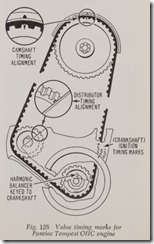
In this engine, the camshaft is driven by a fiber glass reinforced rubber timing belt. Valve timing is correct when all of the marks arc lined up as shown in Fig. 128.
The timing belt can be adjusted as follows:
1. Remove 3 screws on front of top cover. Lift up cover to disengage side clips. Remove retaining clips from cover.
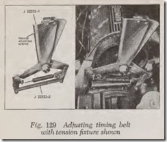
2. Using the tool shown in Fig. 129, set the pointer of the fixture on the zero mark. This calibration must be performed prior to each use of the fixture to insure an accurate belt adjustment.
3. Remove camshaft sprocket-to-camshaft bolt and install the fixture on the belt with the rollers on the outside (smooth) surface of belt. Thread the fixture mounting bolt into camshaft sprocket bolt location finger tight.
4. Squeeze indicator end (upper) of fixture and quickly release so the fixture assumes released or relaxed position.
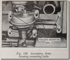
5. With the tool installed as directed, adjust accessory drive housing, Fig. 130, up or down as required to obtain a tension adjuster indi cator centered in the green range with drive housing mounting bolts torqued to 15 ft.-lbs.
6. Remove tension fixture and install sprocket retaining bolt, making sure bolt threads and washer are free of dirt. Install cover.
