Magnetic Starters
When used for starting and control of wound-rotor motors, magnetic starters are built in three different forms, depending on the duty of the motor:
1. Plain starting,
2. Speed regulating,
3. Speed setting.
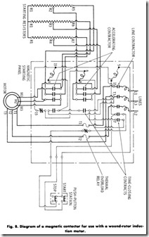
Magnetic starters consist of a magnetic contactor for connecting the stator circuit to the line, and one or more accelerating contactors to commutate the resistance in the rotor circuit . The number of secondary accelerating contactors varies with the rating, a sufficient number being employed to assure smooth acceleration and to keep the inrush current within practical limits. The operation of the accelerating contactors is controlled by a timing device which provides definite time acceleration. For high-voltage service, the primary contactor is usually of the oil-immersed type. The diagram of a typical magnetic starter for use with a wound-rotor induction motor is shown in Fig. 8.
Magnetic-starting speed regulators are very similar to magnetic starters except that the secondary circuit is controlled by a series of magnetic contactors operated from a dial switch in the control station or by a faceplate type of rheostat mounted in the controller itself. Where the magnetic-contactor construction is used, they also act as accelerat ing contactors on starting. If a rheostat is used, accelerating contactors on the panel accelerate the motor up to the speed for which the rheostat is set.
Controller Resistors
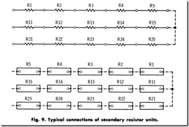
All standard wound-rotor phase circuits, whether for two- or three phase circuits, have their secondaries wound for three-phase. The controller resistors used for each phase are identical with the exception of the terminal marking. The resistor for the first phase has its terminals marked consecutively (R1, R2, RJ, etc.) the second phase Ru, R12, R1J, etc., the third phase R21 ,R22, R2J, etc., as shown in Fig. 9. The actual resistor will consist of one, two, three, or multiples of these frames of tubes or grids.
Secondary resistors for wound-rotor induction motors are, as a rule,designed for star connection. Resistors for most manual controllers may be connected with all three secondary phases closed or with one secondary phase open on the first point of the controller. Resistors for magnetic controllers are connected with all three phases closed in the secondary on the first point. The torque obtained with a resistor of a given class number varies with the connection used on the first point of the controller.
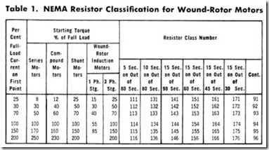
The NEMA resistor classifications for wound-rotor induction motors are given in Table 1. For example, Class 114 is for starting duty only, and for a motor that will be started and brought up to speed in approximately five seconds with a minimum of 75 seconds between successive starts.
The capacity of resistors depends largely on the ventilating space. As a rule, the resistor frames should never be stacked more than four in height, and when space is available, each frame should be separated from the next by approximately the width of the end frame. Frames may be mounted on the floor, platform, or wall, but in such a way as to obtain free ventilation.
It must also be emphasized that a close periodic inspection of resistors and associated connections be made. This inspection should include the tightening of loose lock nuts, connections, etc. The collection of dirt and dust should be blown out from between the resistor units.
APPLICATION
Wound-rotor motors have the ability to start extremely heavy loads. Hence they are suitable for: (1) driving various types of machinery which require development of considerable starting torque to overcome friction; (2) accelerating extremely heavy loads which have a flywheel effect or inertia; and (3) overcoming back pressures set up by fluids and gases in the case of reciprocating pumps and compressors.
Double squirrel-cage motors are also applicable on many of the heavier machines involving the problems mentioned above. However, if a considerable length of time is required to accelerate the load to full speed, double squirrel-cage rotors may burn out before full speed is attained. For that reason, wound-rotor motors should be used instead. Where high starting torque alone is involved, double squirrel-cage motors will qualify, but the fact that all the heat developed in the secondary circuit is confined to the rotor prevents their use if the starting period is too long. Frequent starting has the same effect of overheating double squirrel-cage motors, for which reason wound-rotor motors should be used on machinery started frequently.
Operating Speed Variation
Variations in operating speed are essential on many applications. It is often desirable to vary the operating speed of conveyors, compressors, pulverizers, stokers, etc., in order to meet varying production require ments. Wound-rotor motors, because of their adjustable speeds, are ideally suited for such applications. However, if the torque required does not remain constant, the speed of the wound-rotor motor will vary over wide limits, a characteristic constituting one of the serious objec tions to the use of wound-rotor motors for obtaining reduced speeds. Another factor which must be taken into consideration when wound rotor motors are selected for reduced-speed operations is that of lowered motor efficiency.
This type of motor is suitable where the speed range required is small, where the speeds desired do not coincide with the synchronous speed of the line frequency, or where the speed must be gradually or frequently changed from one value to another.
The wound-rotor motor also gives high starting torque with a low current demand from the line, but it is not efficient when used a large porportion of the time at reduced speed, since power corresponding to the percent of drop in speed is consumed in the external resistance without doing any special work.
The wound-rotor motor can operate at any speed from its maximum full-load speed down to almost standstill. Speed reduction below one-half is not recommended because of poor speed regulation (the no-load speed is always synchronous speed) and because of increased heating of the motor due to the decreased ventilation.
When wound-rotor motors are used for cranes, hoists, and elevators-machinery operated intermittently and for short periods-poor speed regulation and loss in efficiency are of little consequence. How ever, if lowered speed is required over longer periods, poor speed regulation and loss in efficiency may become prohibitive.
Smooth Starting
By the use of external resistors in the slip-ring rotor windings, a wide variation in rotor resistance can be obtained with a resultant variation in acceleration characteristics. Thus, a heavy load can be started as slowly as desired, without jerk, and can be accelerated smoothly and uniformly to full speed. It is merely a matter of supplying the necessary auxiliary control equipment to insert sufficient high resistance at the start, and to gradually reduce this resistance as the motor picks up speed.
Low Starting Current
Many power companies have established limitations on the amount of current that motors may draw at starting. The purpose is to reduce voltage fluctuations and prevent flickering of lights. Because of such limitations, the question of starting current is often the deciding factor in the choice of wound-rotor motors instead of squirrel-cage motors.
Wound-rotor motors, with proper starting equipment, develop a starting torque equal to 150% of full-load torque with a starting current of approximately 150% of full-load current. This compares very favor ably with squirrel-cage motors, one type of which requires a starting current of as much as 600% of full-load current to develop the same starting torque of 150%.
SUMMARY
The stator in the wound-rotor motor is identical to the stator in the squirrel-cage motor. The basic difference in the two motors lies in the rotor winding.
In the squirrel-cage motor, the rotor winding is nearly always self-contained; it is not connected either mechanically or electrically to the outside power-supply or control circuit. However, in wound-rotor motors, the rotor winding consists of insulated coils of wire that are not permanently short-circuited, but are connected in regular succession to form a definite polar area having the same number of poles as the stator.
The ends of these rotor windings are brought out to collector rings, or slip rings.
External resistance in the rotor circuit reduces the speed at which the rotor will operate with a given load torque. If the rotor resistor is designed for continuous duty, a portion may be permitted to remain in the circuit to obtain reduced-speed operation. Therefore, the motor has a varying speed characteristic-any change in load results in a consid erable change in speed.
The wound-rotor motor is often used in cranes, hoists, and elevators. These devices are operated intermittently and for short periods of time, where exact speed regulation and loss in efficiency are of little con sequence.
Wound-rotor motors can be used to start extremely heavy loads.
Hence, they are suitable for: (1) driving various types of machinery which require development of considerable starting torque to overcome friction; (2) accelerating extremely heavy loads which have a flywheel effect or inertia; and (3) overcoming back pressures set up by fluids and gases, as in reciprocating pumps and compressors.
REVIEW QUESTIONS
1. What is the chief difference in the squirrel-cage motor and the wound-rotor motor?
2. How is the wound-rotor motor provided with varying speed characteristic?
3. List five functions of controllers used with wound-rotor motors.
4. List five types of controllers.
5. List three types of equipment that are suitable for wound-rotor motors.


