Wound-Rotor Motors
As far as the stator is concerned, the squirrel-cage motor and the wound-rotor motor are identical. The outstanding difference between the two motors lies in the rotor winding.
In the squirrel-cage motors previously described, the rotor winding is practically self-contained; it is not connected either mechanically or electrically to the outside power-supply or control circuit. It consists of a number of straight bars uniformly distributed around the periphery of the rotor and short-circuited at both ends by end rings to which they are integrally joined. Since the rotor bars and end rings have fixed resis tances, such characteristics as starting and pull-out torques, rate of acceleration, and full-load operating speed cannot be changed for a given motor installation.
In wound-rotor motors, however, the rotor winding consists of insulated coils of wire that are not permanently short-circuited, but are connected in regular succession to form a definite polar area having the same number of poles as the stator. The ends of these rotor windings are brought out to collector rings, or slip rings, as they are commonly termed.
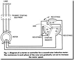
The currents induced in the rotor are carried by means of slip rings (and a number of carbon brushes riding on the slip rings) to an externally mounted resistance which can be regulated by a special control, as indicated in Fig. 1. By varying the amount of resistance in the rotor circuit, a corresponding variation in the motor characteristics can be obtained. Thus, by inserting a high external resistance in the rotor circuit at starting, a high starting torque can be developed with a low starting current. As the motor accelerates to full speed, the resistance is gradually cut out until, at full speed, the resistance is entirely cut out and the rotor windings are short-circuited.
CHARACTERISTICS
By varying the values of resistance in the rotor circuit, the charac teristics of the motor will be affected as follows:
1. Variation in the starting torque and current,
2. Smooth acceleration,
3. Variation in operating speed.
The operating speed depends, of course, entirely on the amount of resistance incorporated in the control equipment.
Fig. 2 shows the speed-torque and corresponding speed-current curves obtainable for a typical wound-rotor induction motor using different values of external rotor resistance. The numbers given on the curves indicate th rotor-circuit resistance in percent of the value required to give full-load torque at standstill.
The curves in Fig. 2 illustrate that external resistance in the rotor circuit reduces the speed at which the rotor will operate with a given load torque. If the rotor resistor is designed for continuous duty, a portion of it may be allowed to remain in the circuit, thus obtaining reduced-speed operation. Therefore, the motor has a varying speed characteristic-that is, any change in load results in a considerable change in speed. It should be borne in mind, however, that the efficiency of a wound-rotor motor, including the 12R losses in the rotor resistance, is reduced in direct proportion to the speed reduction obtained.
Thus, the wound-rotor motor has found its use in cranes, hoists, and elevators. These are operated intermittently and for short periods, where exact speed regulation and loss in efficiency are of little consequence.
If, however, lower speed is required over longer periods, poor speed regulation and loss in efficiency may become prohibitive.
CONTROL EQUIPMENT
From the foregoing it has been determined that wound-rotor motors have certain inherent speed-torque characteristics, and that these can be considerably altered by the secondary control equipment, which in troduces varying values of resistance into the rotor circuit. Since the control equipment has this ability, a further study of the most common types of controllers and associated equipment is appropriate.
The functions of controllers used with wound-rotor motors are:
1. To start the motor without damage or undue disturbance to the motor, driven machine, or power supply,
2. To stop the motor in a satisfactory manner,
3. To reverse the motor,
4. To run the motor at one or more predetermined speeds below synchronous speed,
5. To handle an overhauling load satisfactorily,
6. To protect the motor.
The various types of controllers utilized may be divided into the following groups, depending on the size and function of the motor:
1. Faceplate starters,
2. Faceplate speed regulators,
3. Multiswitch starters,
4. Drum controllers,
5. Motor-driven drum controllers,
6. Magnetic starters.
Faceplate Starters
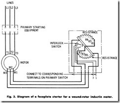
A typical wiring diagram of a combined faceplate starter and speed is shown in Fig. 3. This particular type requires a separate switch for control of the primary circuit. Faceplate starters are usually adaptable for motors up to 50 hp (37. 3 kW) where the full-load current in the rotor circuit is less than 150 amperes.
As shown in the diagram, the resistance is made up of three delta-connected sections, but is connected in two phases only, the third being a fixed step. The starting lever is equipped with a spring similar to that used in de motor starters. The spring returns the lever to the starting (all-resistance) position when it is released. As an additional safety feature, the contact arm or lever cannot be left in the full-in position unless the primary (stator) contactor is closed; nor can it be left in an intermediate position at any time.
Faceplate Speed Regulators
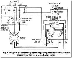
A typical wiring diagram of a combined faceplate starter and speed regulator for use in the rotor circuit of wound-rotor induction motors is shown in Fig. 4. Starters of this type usually provide for a 50% speed reduction when the motor operates under full load at normal speed. They are usually built for motors in sizes up to 40 hp (29.84 kW) and for rotor currents up to 100 amperes. Since the starter is not connected with the primary circuit of the motor, a magnetic switch, an oil circuit breaker, or similar device must be installed to control the primary circuit.
Mu ltiswitch Starters
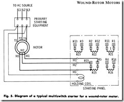
Multiswitch starters are used in the secondary circuit of large wound-rotor induction motors up to 2000 hp (1492 kW) with rotor currents up to 1000 amperes. A typical wiring diagram of a multiswitch starter is shown in Fig. 5.
The type of switch to be used in the primary (stator) circuit depends on the voltage of the supply source. The resistor units in the secondary (rotor) circuit are balanced on all steps of the controller. The contact levers are of the double-pole type and are mechanically arranged in such a manner that they must be closed in a predetermined sequence, and only one at a time. Since the switches are designed for hand-over-hand operation, a desirable time element is introduced which prevents too rapid acceleration of the motor. When the final switch has been closed, it is held in place by a magnetic coil, and because of the mechanical interlocking feature, all other switches remain closed.
A failure of the motor supply source will cause the magnet coil to release the switches, returning the starter to the starting position with all the resistance in the secondary circuit. This type of starter is designed for starting duty only and is not suitable where speed regulation is required.
Drum Controllers
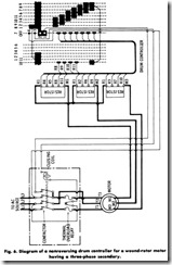
Drum controllers (Fig. 6) are frequently employed for starting and for speed control of wound-rotor induction motors. Because of their con struction features, they offer a compact, sturdy, and dependable control means and also add to the safety of the operator. Drum controllers are built to handle both stator and rotor circuits, the cylinder mounting the contact segments being built in two insulated sections. They are also built to handle the rotor circuit only, in which case the stator circuit is controlled by a circuit breaker or line starter. Other types are being built for operation by means of an independent motor. In addition to starting and regulating, speed-regulating drum collectors are commonly used for speed-reversing duty as well.
On small- and medium-sized motors, the faceplate starters described earlier are commonly used, but with large motors, drum controllers are generally preferred because their contacts are heavier and better able to handle the heavy currents required.
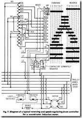
Fig. 7 shows the connections of a typical drum controller for reversing and speed-regulation duty with a wound-rotor motor. The resistor material is mounted separately from the drum, and connections from the resistor are brought to the drum fingers.
The resistor connections shown in Fig. 7 are for starting the motor with one phase of its secondary open on the first point of the controller.
When higher starting torque is desired, or when connecting a motor that is rated above 80 hp (59.68 kW) connect R1 to R11 at the resistor and the finger marked R1 on the controller to terminal RJ on the resistors. Resistor steps R5 to R6, R15 to R16, and R25 to R26 are for resistances which remain permanently in the circuit. When these are not furnished, connect M,M2, and MJ to R5, R15, and R25 as indicated by the dotted lines.
Motor-driven drum controllers are used in certain drives requiring close automatic speed regulation such as in large air-conditioning plants, blowers, stokers, etc. In construction, these controllers differ from those previously described in that cam-operated switches are used in place of the segments and fingers.
These drums are built with either 13 or 20 balanced speed-regulating points, and the cam-switch construction saves space when so many balanced points are needed. Each switch carries two contacts, both of which are connected to the middle leg of the resistor. They make contact simultaneously with stationary contacts, one connected to each of the outside legs of the resistor. In this way, the closing of any cam-operated switch short-circuits the resistor at that point. The drum is driven by a small motor connected to the drum shaft through suitable gearing. The pilot motor is energized by some automatic device, such as a thermostat or a regulator.
A typical motor-driven drum may have 20 balanced speed points and be rated at 600 amperes and 1000 volts. It may have a positioning device which ensures that the pilot motor stops only at positions in which the switches are fully closed. It may also have self-contained limit switches are fully closed. It may also have self-contained limit switches which open to stop the motor at each end of the drum travel.
