Voltage Control
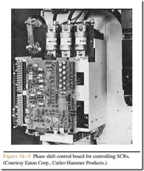
Output voltage control is achieved by phase shifting the SCRs. The phase shift control unit determines the output voltage of the rectifier (Figure 34 – 4). Since the phase shift unit is the real controller of the circuit, other sections of the circuit provide information to the phase shift control unit. Figure 34 – 5 shows a typical phase shift control unit.
Field Failure Control
As stated previously, if current flow through the shunt field is interrupted, a compound wound, DC motor will become a series motor and race to high speeds. Some
method must be provided to disconnect the armature from the circuit in case current flow through the shunt field stops. Several methods can be used to sense
current flow through the shunt field. In Chapter 33, a current relay was connected in series with the shunt field. A contact of the current relay was connected in series with the coil of a motor starter used to connect the armature to the power line. If current flow were stopped, the contact of the current relay would open, causing the circuit of the motor starter coil to open.
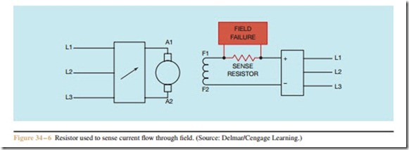
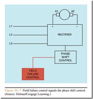
Another method used to sense current flow is to connect a low value of resistance in series with the shunt field (Figure 34 – 6). The voltage drop across the sense resistor is proportional to the current flowing through the resistor (E = I X R). Since the sense resistor is connected in series with the shunt field, the current flow through the sense resistor must be the same as the current flow through the shunt field. A circuit can be designed to measure the voltage drop across the sense resistor. If this voltage falls below a certain level, a signal is sent to the phase shift control unit and the SCRs are turned off (Figure 34 – 7).


