Measuring current
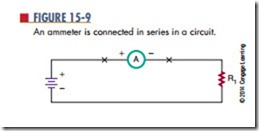
To use an ammeter to measure current, the circuit must be opened and the meter inserted into the circuit in series (Figure 15-9).
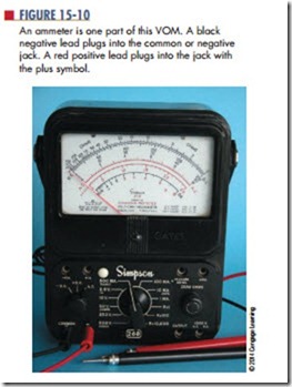
When placing the ammeter in the circuit, polarity must be observed. The two terminals on an ammeter are marked: red for positive and black for negative (or common) (Figure 15-10).
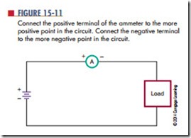
The negative terminal must be connected to the more negative point in the circuit, and the positive terminal to the more positive point in the circuit (Figure 15-11). When the ammeter is connected, the needle (pointer) of the meter moves from left to right. If the needle moves in the opposite direction, reverse the leads.
Another way to measure current that does not re- quire opening the circuit and placing an ammeter in series is to use a resistor of a known value in the circuit. The resistor is referred to as an ammeter shunt and may be installed by the manufacturer or inserted for temporary use. The resistor may be left in for future testing of the circuit and must be of a small enough value to not interfere with the normal operation of the circuit.
The resistor’s purpose is to provide a small output voltage for measuring. The best meter to use is a DMM because it is able to accurately measure small voltages.
Ohm’s law (I 5 E/R) is used to calculate the amount of current measured by the shunt. Dividing the voltage read by the resistance value yields the current flowing in the circuit.
Figure 15-12 shows a 0.1 Ω resistor used as a shunt. If the DMM reads 330 mV, then the circuit has 3.3 A flowing through it.
The advantage of using this technique is that the circuit does not have to be opened and an ammeter inserted. Also note that voltage—rather than current— was read.
Before turning on power to the circuit after the am- meter is installed, set the meter to its highest scale (its highest ammeter range before applying power). After the power is applied, the ammeter can be set to the appropriate scale. This prevents the needle of the meter from being driven into its stop.
The internal resistance of the ammeter adds to the circuit and increases the total resistance of the circuit. Therefore, the measured circuit current can be slightly lower than the actual circuit current. How- ever, because the resistance of an ammeter is usually minute compared to the circuit resistance, the error is ignored.
A clip-on ammeter requires no connection to the circuit being measured and uses the electromagnetic field created by the current flow to measure the amount of current in the circuit.
Questions
1. How is an ammeter connected to a circuit?
2. What is the first step before connecting an ammeter in a circuit?
3. What should be done if the ammeter reads in the reverse direction?
4. What scale should the ammeter be placed on before applying power?
Why should an ammeter never be connected in parallel in a circuit?


