Digital Filtering
Although it may be clear that the multiplication process controls the signal level, it is not immediately obvious that the multiplicative process is intrinsic to any form of filtering. Thus multipliers are at the heart of any significant digital signal processing, and modern digital signal processing would not be possible without the availability of suitable IC technology. You will need to accept, at this stage, that the process of representing an analogue audio signal in the form of a sequence of numbers is readily achieved and thus we are free to consider how the equivalent analogue processes of filtering and equalization may be carried out on the digitized form of the signal.
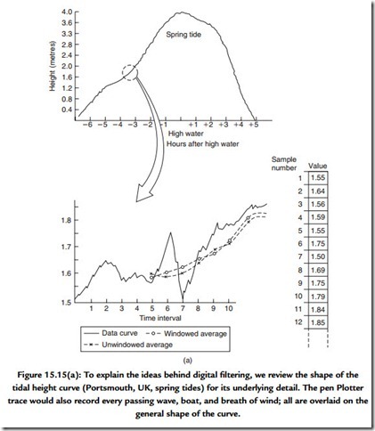
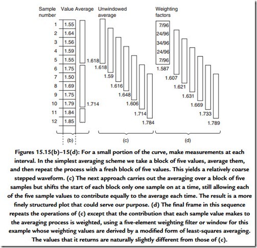
In fact, the processes required to perform digital filtering are performed daily by many people without giving the process much thought. Consider the waveform of the tidal height curve of Figure 15.15. The crude method by which we obtained this curve (Figure 15.1) contained only an approximate method for removing the effect of ripples in the water by including a simple dashpot linked to the recording mechanism. If we were to look at this trace more closely we would see that it was not perfectly smooth due to local effects such as passing boats and wind-driven waves. Of course tidal heights do not normally increase by 100 mm within a few seconds and so it is sensible to draw a line that passes through the average of these disturbances. This averaging process is filtering and, in this case, it is an example of low-pass filtering. To achieve this numerically we could measure the height indicated by the tidal plot each minute and calculate the average height for each 4-min span (and this involves measuring the height at five time points):
Done simply, this would result in a stepped curve that still lacks the smoothness of a simple line. We could reduce the stepped appearance by using a moving average in which we calculate the average height in a 4-min span but we move the reference time forward by a single minute each time we perform the calculation. The inclusion of each of the height samples was made without weighting their contribution to the average and this is an example of rectangular windowing. We could go one step further by weighting the
contribution that each height makes to the average each time we calculate the average of a 4-min period. Shaped windows are common in the field of statistics and are used in digital signal processing. The choice of window does affect the result, although as it happens the effect is slight in the example given here.
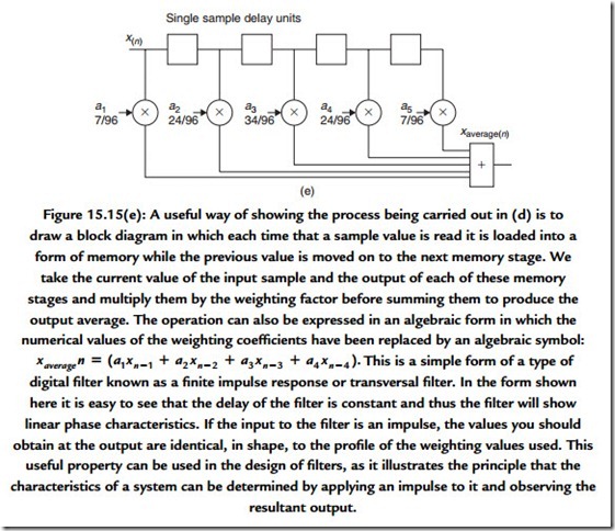
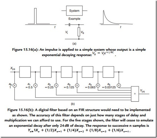
One major practical problem with implementing practical finite impulse response (FIR) filters for digital audio signals is that controlling the response accurately or at low
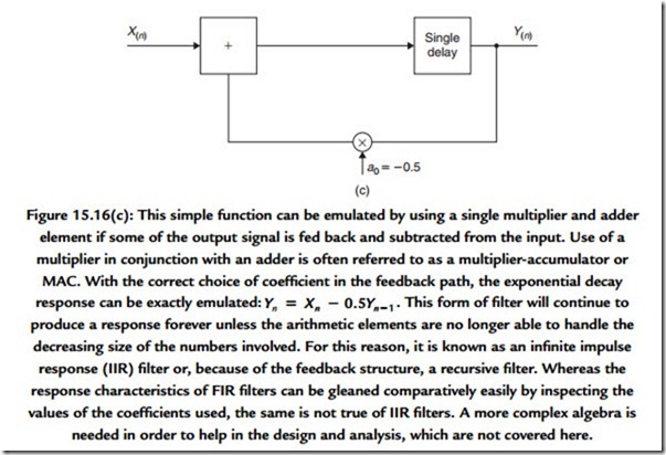
frequencies forces the number of stages to be very high. You can appreciate this through recognizing that the FIR filter response is determined by the number and value of the coefficients applied to each of the taps in the delayed signal stages. The value of these coefficients is an exact copy of the filter’s impulse response. Thus an impulse response intended to be effective at low frequencies is likely to require a great many stages. This places pressure on the hardware that has to satisfy the demand to perform the necessary large number of multiplications within the time allotted for processing each sample value. In many situations a sufficiently accurate response can be obtained with less circuitry by feeding part of a filter’s output back to the input (Figure 15.16).
We have drawn examples of digital filtering without explicit reference to their use in digital audio. The reason is that the principles of digital signal processing hold true no matter what the origin or use of the signal being processed. The ready accessibility of analogue audio “cook-books” and the simplicity of the signal structure have drawn a number of less than structured practitioners into the field. For whatever inaccessible reason, these practitioners have given the audio engineer the peculiar notions of directional copper cables, especially colored capacitors, and compact discs outlined with green felt tip pens. Bless them all, they have their place as entertainment and they remain free in their pursuit of the arts of the audio witch doctor. The world of digital processing
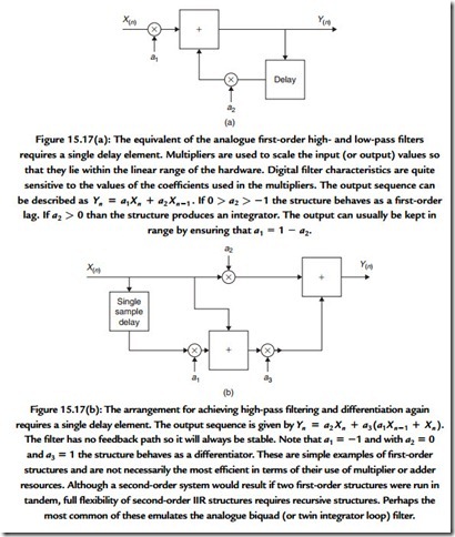
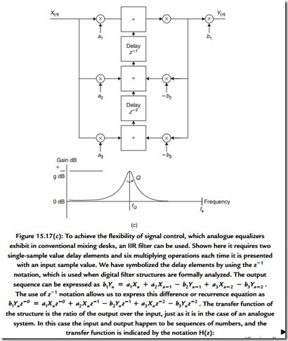
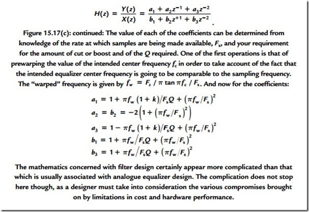
requires more rigor in its approach and practice. Figure 15.17 shows examples of simple forms of first- and second-order filter structures. Processing an audio signal in the digital domain can provide a flexibility that analogue processing denies. You may notice from the examples how readily the characteristics of a filter can be changed simply by adjustment of the coefficients used in the multiplication process. The equivalent analogue process would require much switching and component matching. Moreover, each digital filter or process will provide exactly the same performance for a given set of coefficient values, which is a far cry from the miasma of tolerance problems that beset the analogue designer.
The complicated actions of digital audio equalization are an obvious candidate for implementation using infinite impulse response filters and the field has been heavily researched in recent years. Much research has been directed toward overcoming some of the practical problems, such as limited arithmetic resolution or precision and limited processing time. Practical hardware considerations force the resulting precision of any digital arithmetic operation to be limited. The limited precision also affects the choice of
values for the coefficients whose value will determine the characteristics of a filter. This limited precision is effectively a processing error, which will make its presence known through the addition of noise to the output. The limited precision also leads to the odd effects for which there is no direct analogue equivalent, such as limit cycle oscillations. The details concerning the structure of a digital filter have a very strong effect on the sensitivity of the filter to noise and accuracy, in addition to the varying processing resource requirement. The best structure thus depends a little on the processing task that is required to be carried out. The skill of the engineer is, as ever, in balancing the factors in order to optimize the necessary compromises.
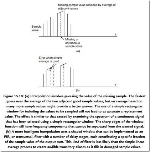
While complicated filtering is undoubtedly used in digital audio signal processing, spare a thought for the simple process of averaging. In digital signal processing terms this is usually called interpolation (Figure 15.18). The process is used to conceal unrecoverable errors in a sequence of digital sample values and, for example, is used in the compact disc for just this reason.

