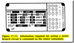
A motor branch circuit consists of several different parts that must be sized properly. The motor is unique because it draws a very high starting current in comparison to the full load running current. The motor also rna) stall or break down while in operation. Means must bE provided to disconnect power, usually automatically, if’ failure occurs. The components of most motor circuit~ are shown in a diagram at the beginning of NEC Articlt 430. Information supplied on the motor nameplate i~ necessary for sizing the circuit components
• Branch-circuit disconnect
• Branch-circuit short-circuit and ground-fault protection
• Branch-circuit wires
• Motor controllet
• Motor running overload protection
• Motor control circuit where a magnetic motor starter i used
Sizing the motor branch circuit begins with the moto nameplate. Consider the motor nameplate of Figure 17 13. The motor is 3 phase, dual voltage. First, determin the type of electrical supply available. Assume, in this case, that the electrical supply is 240 V, 3 phase. The motor full load current therefore, will be 19.2 A
The type of electrical equipment from which the motor circuit will originate must be determined. Common sources of electrical power for electric motors are:
1. Circuit-breaker panelboards
2. Fusible panelboards
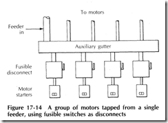
3. Fusible disconnects tapped from a feeder, Figure 17-14
4. Fusible disconnects tapped from a bus duct
MOTOR FULL – LOAD CURRENT
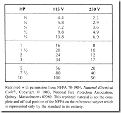
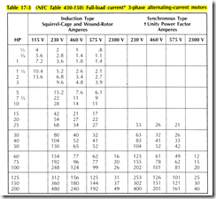
The motor full load current that is used to determine the minimum size of motor circuit components is the current listed in NEC Tables 430 148 and 430 150 (Tables 17 2 and 17 3 in this text), NEC Section 430 6(a). However, this value should be checked against the motor nameplate ampere rating. Sometimes a farm motor may have an ampere rating higher than the value listed in the NEC Tables. In this situation, the higher of the values should be taken for sizing components, (See notes to Tables 17 2 and 17 3)
The nameplate current rating must be used for selecting the maximum size motor running overload protection. This is important because the overload heaters must be sized for a specific motor. If motors are changed, then the overload heaters may have to be changed. The full load current for a 3 phase, 208 V electric motor is not listed in NEC Table 430 150. The footnote at the bottom of the table tells how to obtain the correct value. Actually, a 208 V motor usually operates at about 200 V. The correct value is determined by multiplying the full load current for a 230 V motor by 1.15. For example, a 200 V, 10 hp motor would draw 32 A
Table 17 2 (NEC Table 430 148) Full load currents in amperes; single phase alternating current motors
The following values of full load currents are for motors running at usual speeds and motors with normal torque characteristics. Motors built for especially low speeds or high torques may have higher full load currents, and multi . speed motors will have full load current varying with speed, in which case the name plate current ratings shall be used
To obtain full load currents of 208 and 200 volt motors, increase corresponding 230 volt motor full load currents by 10 and 1 5 percent, respectively. The voltages listed are rated motor voltages. The currents Iisted shall be permitted for system voltage ranges of 110 to 120 and 220 to 240
For full load currents of 208 and 200 volt motors, increase the corresponding 230 volt motor full load current by 10 and 15 percent, respectively
These values of full load current are for motors running at speeds usual for belted motors and motors with normal torque characteristics. Motors built for especially low speeds or high torques may require more running current, and multispeed motors will have full load current varying with speed, in which case the nameplate current rating shall be used
For 90 and 80 percent power factor the above figures shall be multiplied by 1.1 and 1.25 respectively.
The voltages listed are rated motor voltages. The currents listed shall be permitted for system voltage ranges of 110 to 120, 220 to 240, 440 to 480, and 550 to 600 volts
Reprinted with permission from NFPA 70 1984, National Electrical Code®, Copyright© 1983, National Fire Protection Association, Quincy, MA. This reprinted material is not the complete and official position of the NFPA on the referenced subject which is represented only by the standard in its entirety


