Understanding the operation and components of a magnetic motor starter is important when wiring a motor circuit, as well as when performing repairs when there is a malfunction. Only one manufacturer’s motor starter is shown in the text, but all have essentially the same features.
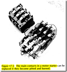
The main contacts, Figure 17 5, are inside the main part of the starter. After many years of service, these contacts may become pitted and burned from the arcing as they open the circuit. Replacement kits for the main contacts are available.
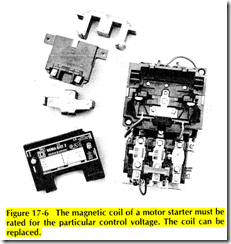
Electrical power supplied to the coil of the solenoid closes the motor starter contacts. The coil must be rated for the voltage of the control circuit electrical supply, Figure 17 6. Typical voltages are 24, 120, 208, 240, 277, and 480 volts. A coil is replaceable. If the coil becomes damaged, only the coil need be replaced. The steel solenoid core fits all coils made for the particular size and model of motor starter
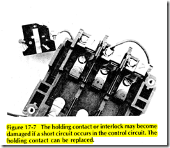
An auxiliary holding contact, Figure 17 7, is supplied with the motor starter. It is required when a startstop station is used as the control device. The holding contact is replaceable should a short circuit occur in the control wiring, causing damage to the holding contact.
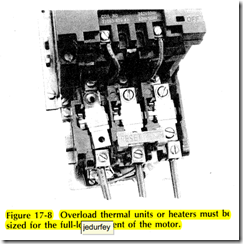
An overload relay section is added to the motor starter to sense motor current. This entire unit can be removed from the motor starter, Figure 17 8. A normally closed contact is usually sealed inside the overload section. Some models have one normally closed contact, while others have two or three. If this section becomes damaged, the entire section usually must be replaced
Heating elements are added to this section sized for the nameplate full load current of the motor. These overload heaters are replaceable.
NEMA SIZES
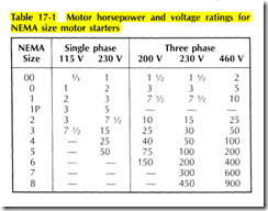
The National Electrical Manufacturers Association (NEMA) has developed a standard numbering system fo; motor starter sizes. The same numbering system is used by all manufacturers. The sizes range from 00 to 8. The larger the number, the greater is the horsepower rating of the starter. The starters are rated according to the current they will be expected to carry continuously, and interrupt if the motor should stall. The motor current depends upon the supply voltage. Naturally then, a given size of motor starter could handle a higher horsepower motor at 460 V than at 230 V. NEMA sizes and horsepower ratings are given in Table 17 1
Motor starters are available with two poles or three poles. The 2 pole motor starter is used for single phase motors. Two pole motor starters are usually available up to NEMA size 3. A 3 pole motor starter may be used for either a 3 phase motor or a single phase motor. If a 3 pole starter is used for a single phase motor, only two of the three poles are used. The third pole is simply ignored. Since 3 pole motor starters are more readily available than 2 pole starters, this is a common practice.
Single phase and 3 phase horsepower ratings on a motor starter are not equivalent. NEMA sizes are equivalent, however, insofar as the current they will handle. Some 3 pole motor starters list both the single phase and polyphase horsepower ratings, others do not. There is a simple rule that should be followed: A 3 pole motor starter will handle a single phase motor with a horsepower rating ~nly half as large as a 3 phase motor. For example, a NEMA size 2 3 pole motor starter will handle a 15 hp, 230 V, 3 phase motor. The same size motor starter is capable of handling only a 7lf2 hp, singlephase, 230 V motor. The reason is clear when the fullload current for each motor is compared from NEC Tables 430 148 and 430 150. This rule does not hold true exactly, however, for the NEMA small sizes 00 and 0, as shown in Table 17 1. For sizes 1 and larger, the horsepower essentially doubles as the size number is increased by I.
NEMA ENCLOSURE TYPES
The enclosure for housing the motor starter is selected for the type of environment in the area. NEMA has developed a standard numbering system for types of electrical equipment enclosures.
The enclosure type, except NEMA 1 , is required to be marked on motor starter enclosures, NEC Section 430 91. This is a recent Code requirement; therefore, most motor starters presently in use are not so marked. NEC Table 430 91 gives NEMA enclosure types for motor starters, listing the outdoor and indoor conditions for which they are suitable.
Common enclosures used for agricultural, commercial, and industrial locations are as follows
NEMA 1: General purpose enclosure used in any location that is dry and free from dust and flying flammable materials, Figure 17 9
NEMA 3: Weather resistant enclosure which is suitable for use outdoors. Not suitable for use in dusty locations.
NEMA 4: Watertight and dusttight enclosure suitable for outdoor locations as well as inside wet locations. Water can be sprayed directly on the enclosure without it leaking inside. Suitable for most agricultural locations provided corrosion is not a problem.
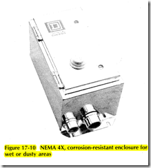
NEMA 4X: Watertight, dusttight, and corrosion resistant enclosure suitable for outside and inside wet, dusty, and corrosive areas. Suitable for agricultural buildings. Available with stainless steel and nonmetallic enclosures, Figure 17 1 0.
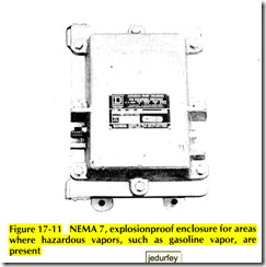
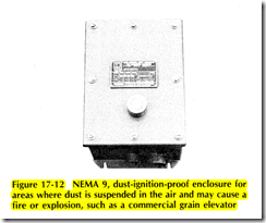
NEMA 7: Explosionproof enclosure suitable for installation in Class I areas containing hazardous vapors. Must also be rated for the type of hazardous vapor, such as gasoline vapor, Group D, Figure 17 1 1 dust, Group G, Figure 17 12. Some manufacturers build one enclosure rated as NEMA 7 and 9
NEMA 12: Dusttight, driptight, and oil retardant enclosure suitable for machine tools and areas where there are flammable flying particles, such as in cotton gins and textile processing and handling operations
