The Record-Replay System
The Recording System Layout
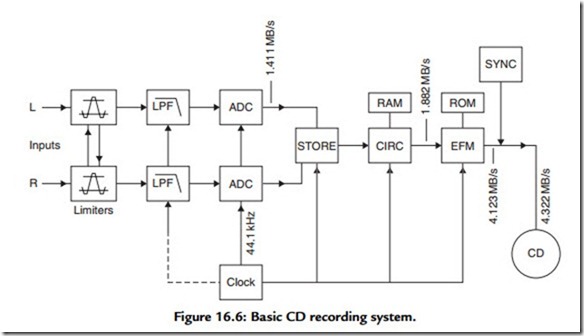
How the signal is handled, on its way from the microphone or other signal source to the final CD, is shown in the block diagram of Figure 16.6. Assuming that the signal has by now been reduced to a basic L–R stereo pair, this is amplitude limited to ensure that no signals greater than the possible encoding amplitude limit are passed on to the analogue-to-digital converter (ADC) stage. These input limiter stages are normally cross linked in operation to avoid disturbance of the stereo image position if the maximum permitted signal level is exceeded, and the channel gain reduced in consequence of this, in only a single channel.
The signal is then passed to a very steep-cut 20-kHz antialiasing filter (often called a “brick wall filter”) to limit the bandwidth offered for encoding. This bandwidth limitation
is a specific requirement of the digital encoding/decoding process, for the reasons already considered. It is necessary to carry out this filtering process after the amplitude limiting stage because it is possible that the action of peak clipping may generate additional
high-frequency signal components. This would occur because “squaring off” the peaks of waveforms will generate a Fourier series of higher frequency harmonic components.
The audio signal, which is still at this stage in analogue form, is then passed to two parallel operating 16-bit ADCs and, having now been converted into a digital data stream, is fed into a temporary data-storage device—usually a “shift register”—from which the output data stream is drawn as a sequence of 8-bit blocks, with the ‘L’ and ‘R’ channel data now arranged in a consecutive but interlaced time sequence.
From the point in the chain at which the signal is converted into digitally encoded blocks of data, at a precisely controlled “clock” frequency, to the final transformation of the encoded data back into analogue form, the signal is immune to frequency or pitch errors as a result of motor speed variations in the disc recording or replay process.
The next stage in the process is the addition of data for error correction purposes. Because of the very high packing density of the digital data on the disc, it is very likely that the recovered data will have been corrupted to some extent by impulse noise or blemishes, such as dust, scratches, or thumb prints on the surface of the disc, and it is necessary to include additional information in the data code to allow any erroneous data to be corrected. A number of techniques have been evolved for this purpose, but the one used in the CD is known as the “cross-interleave Reed–Solomon code” (CIRC). This is a very powerful error correction method and allows complete correction of faulty data arising from quite large disc surface blemishes.
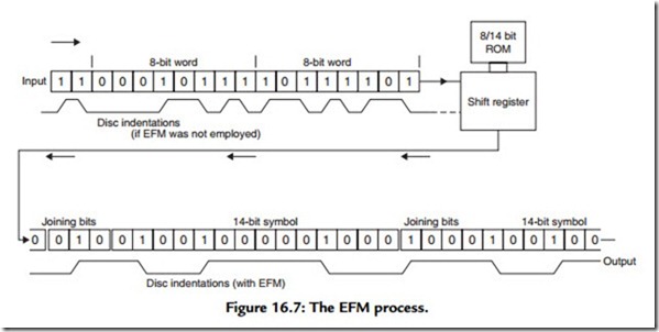
Because all possible ‘0’ or ‘1’ combinations may occur in the 8-bit encoded words, and some of these would offer bit sequences rich in consecutive ‘0’s or ‘1’s, which could embarrass the disc speed or spot and track location servo-mechanisms, or, by inconvenient juxtaposition, make it more difficult to read the pit sequence recorded on the disc surface, a bit-pattern transformation stage known as the “eight to fourteen modulation” (EFM) converter is interposed between the output of the error correction (CIRC) block and the final recording. This expands the recorded bit sequence into the form shown in Figure 16.7 to facilitate the operation of the recording and replay process. The functions and method of operation of all these various stages are explained in more detail later in this chapter.
Disc Recording
This follows a process similar to that used in the manufacture of vinyl EP and LP records, except that the recording head is caused to generate a spiral pattern of pits in an optically
flat glass plate, rather than a spiral groove in a metal one, and that the width of the spiral track is very much smaller (about 1/60th) than that of the vinyl groove. (Detail of the CD groove pattern is, for example, too fine to be resolved by a standard optical microscope.) When the master disc is made, “mother” and “daughter” discs are then made preparatory to the production of the stampers, which are used to press out the track pattern on a thin (1.4 mm) plastics sheet, prior to the metallization of the pit pattern for optical readout in the final disc.

