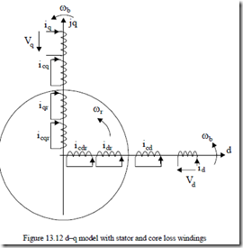
To include the core loss in the space phasor model of IMs, we assume that the core losses occur, both in the stator and rotor, into equivalent orthogonal windings: cd – cq, cdr – cqr (Figure 13.12).
Alternatively, when rotor core loss is neglected (cage rotor IMs), the cdr – cqr windings account for the skin effect via the double-cage equivalence principle.
Let us consider also that the core loss windings are coupled to the other windings only by the main flux path.
The space phasor equations are thus straightforward (by addition).
R is s −Vs = − ddtΨs − ω Ψj b s; Ψ = Ψs m + L ils s
R ics cs = − dΨdtcs − ω Ψj b cs; Ψcs = Ψm + Llcsics (13.66)
R ir r −Vr = − ddtΨr − j(ω −ω Ψb r ) r; Ψ = Ψr m + L ilr r
|
R icr cr = − ddtcr − j(ω −ω Ψb r ) cr; Ψcr = Ψm + Llcricr |
|
|
(13.67) |
Ψ
The airgap torque now contains two components, one given by the stator current and the other one (braking) given by the stator core losses. Te = 3 p Re j1 [(Ψs si * + Ψcs csi * )]= 3 p Re j1 [ Ψm (is* +ics* )] (13.68)
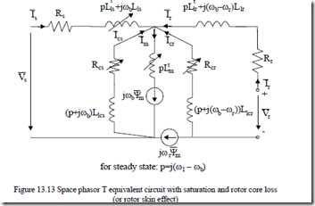
Equations (13.66) and (13.67) lead to a fairly general equivalent circuit when we introduce the transient magnetization inductance Lmt (13.65) and consider separately main flux and leakage paths saturation (Figure 13.13). The apparently involved equivalent circuit in Figure 13.13 is fairly general and may be applied for many practical cases such as
• The reference system may be attached to the stator, ωb = 0 (for cage rotor and large transients), to the rotor (for the doubly fed IM), or to stator frequency ωb = ω1 for electric drives transients.
• ![]() To simplify the solving of Equations (13.66) and (13.67) the reference system may be attached to the main flux space phasor: Ψm = Ψm ( )im and eventually using im, ics, icr, ir, ωr as variables with is as a dummy variable. [7,8] As expected, d–q decomposition is required.
To simplify the solving of Equations (13.66) and (13.67) the reference system may be attached to the main flux space phasor: Ψm = Ψm ( )im and eventually using im, ics, icr, ir, ωr as variables with is as a dummy variable. [7,8] As expected, d–q decomposition is required.
• For a cage rotor with skin effect (medium and large power motors fed from the power grid directly), we should simply make Vr = 0 and consider the rotor core loss winding (with its equations) as the second (fictitious) rotor cage.
Example 13.2. Saturation and core losses
Simulation results are presented in what follows. The motor constant parameters are: Rs = 3.41Ω, Rr = 1.89Ω, Lsl = 1.14⋅10-2H, Lrl = 0.9076⋅10-2H, J =
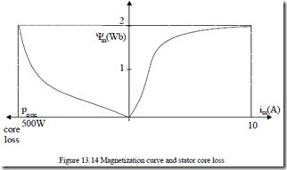
6.25⋅10-3Kgm2. The magnetization curve Ψm(im) is shown in Figure 13.14 together with core loss in the stator at 50 Hz.
The stator core loss resistance Rcs
Rcs = 32 ω Ψ1P2ironm2 ≈ 23 (2π50500)2 ⋅22 =1183.15Ω
Considering that Llcs⋅ω1 = Rcs; Llcs = 1183.15/(2π50) = 3.768 H.
For steady-state and synchronous coordinates (d/dt = 0), Equations (13.66) become
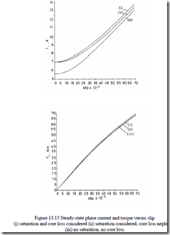
![]() For given values of slip S, the values of stator current is0 / 2 (RMS/phase) and the electromagnetic torque are calculated for steady-state making use of (13.69) and the flux/current relationships (13.66) and (13.67) and Figure 13.14.
For given values of slip S, the values of stator current is0 / 2 (RMS/phase) and the electromagnetic torque are calculated for steady-state making use of (13.69) and the flux/current relationships (13.66) and (13.67) and Figure 13.14.
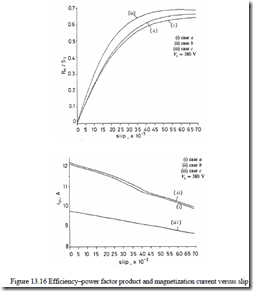
The results are given in Figure 13.15a and b. There are notable differences in stator current due to saturation. The differences in torque are rather small. Efficiency–power factor product and the magnetization current versus slip are shown in Figure 13.16a and b.
Again, saturation and core loss play an important role in reducing the efficiency–power factor although core loss itself tends to increase the power factor while it tends to reduce the efficiency.
reduction of magnetization current im with slip is small but still worth considering.
Two transients have been investigated by solving (13.66) and (13.67) and the motion equations through the Runge–Kutta–Gill method.
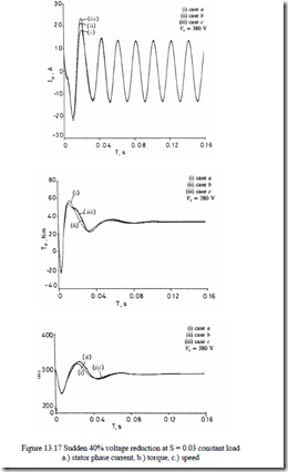
1. Sudden 40% reduction of supply voltage from 380 V per phase (RMS), steady-state constant load corresponding to S = 0.03.
2. Disconnection of the loaded motor at S = 0.03 for 10 ms and reconnection
(at δ0 = 0, though any phasing could be used). The load is constant again.
The transients for transient 1 are shown in Figure 13.17a, b, c.
Some influence of saturation and core loss occurs in the early stages of the transients, but in general the influence of them is moderate because at reduced voltage, saturation influence diminishes considerably.
The second transient, occurring at high voltage (and saturation level), causes more important influences of saturation (and core loss) as shown in Figure 13.18a, b, c.
The saturation and core loss lead to higher current peaks, but apparently for low torque and speed transients.
In high-performance variable-speed drives, high levels of saturation may be inflicted to increase the torque transient capabilities of IM. Vector control detuning occurs and it has to be corrected. Also, in very precise torque control drives, such second order phenomena are to be considered. Skin effect also influences the transients of IMs and the model on Figure 13.13 can handle it for cage rotor IMs directly as shown earlier in this paragraph.
