Components of Fuel System
The fuel system consists of:
1. A tank for storing the fuel.
2. A fuel gauge on the instrument panel which keeps the driver informed as to the amount of fuel in the tank.
3. Pipes for conveying the fuel from the tank to the engine.
4. Filters and cleaners for straining and cleaning the air and fuel.
5. A fuel pump for transferring the fuel from the tank to the carburetor.
6. A carburetor which feeds the engine with a vaporized mixture of fuel and air.
7. An intake manifold which forms a path for fuel mixture to flow to the engine’s combustion chambers.
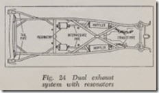
8. The exhaust system consisting of the exhaust manifolds, which directs the burned gases through exhaust pipe, muffier and tailpipe to the atmosphere. Frequently a smaller muffier, called a resonator, is installed toward the end of the tailpipe.
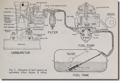
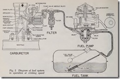
Figs. 1 and 2 show how the fuel travels through the system when the engine is idling and when cruising along.
FUEL TANKS
Since all modern fuel systems are pump fed, the fuel tank can be placed at the most convenient point in the vehicle-which is at the rear of the chassis under the trunk compartment of the car. The exception of this is the rear engined Corvair which has the fuel tank in the1 forward com partment.
The tank has an inlet or filler pipe, and an outlet. The outlet, with a fitting for fuel line con nection, may be in the top or side of the tank. The lower end of the outlet pipe is placed about one half inch from the bottom of the tank so that any sediment which collects in the tank will not be carried to the carburetor. Baffie plates may be placed in the tank to reinforce the sides and bottom and to prevent the fuel from surging or splashing. The baffics arc welded to the sides and bottom and are notched or perforated so that the fuel can flow freely from one section to the other.
A drain plug is placed in the bottom so the tank can be drained and cleaned.
FUEL FILTERS
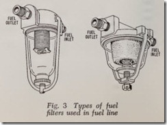
These may be located any place between the fuel tank and carburetor, Fig. 3. One may be in the tank itself, in the fuel pump or in the car buretor.
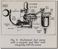
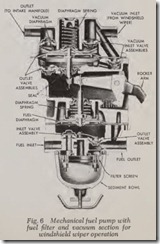
The most common type of fuel filter, shown in Figs. 5 and 6, is placed between the fuel tank and mechanical fuel pump. In this type, the fuel enters the glass bowl and passes up through the filter screen and out through the outlet. Any water or solid matter caught by the filter fall to the bottom of the glass filter bowl where they can be readily seen and removed. Dirt in fuel generally comes from rust scale in tank cars, storage tanks or drums. Water comes from condensation of mois ture in the fuel tank.
FUEL PUMPS
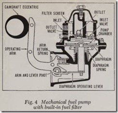
Mechanical fuel pumps are of the diaphragm type shown in Figs. 4 and 5. Fig. 6 differs in that the pump has a vacuum booster section. This booster section has nothing to do with the fuel system, except that it is operated by the fuel pump arm. In Fig. 4, the inlet valve and filter are built in the body of the pump, and in the other two types, Figs. 5 and 6, the inlet valve and filter
are separate from the pump body but are part of the assembly.
Mechanical Fuel Pump Operation During the first or suction stroke, the rotation of the eccentric on the camshaft actuates the pump operating arm, which pulls the lever and dia phragm downward against the pressure of the diaphragm spring, producing a suction (vacuum) in the pump chamber. The suction holds the outlet valve closed and pulls the inlet valve open, making the fuel flow from the supply tank through the inlet up through the filter screen and down through the inlet valve into the pump chamber. During the return stroke, the diaphragm is forced up by the diaphragm spring, the inlet valve closes and the outlet valve is forced open, allowing the fuel to flow through the outlet to the carburetor.
The operating lever is hinged to the pump arm so that it can be moved down but cannot be raised by the pump arm. The pump arm spring makes the arm follow the cam without moving the lever. The lever is only moved upward by the diaphragm spring. The pump, therefore, only de livers fuel to the carburetor when the fuel pres sure in the outlet is less than the pressure main tained by the diaphragm spring. This condition arises when the fuel passage from the pump into the carburetor float chamber is open and the float needle valve is not seated. The foregoing descrip tion can be followed by referring to the fuel pump shown in Fig. 5.
Electric Fuel Pump Operation
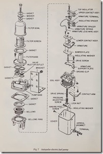
While electrically operated fuel pumps have been used for many years on trucks, buses, etc., and as replacements for mechanically operated fuel pumps on automobiles, they have only re cently become original equipment on cars. The replacement types, of which Fig. 7 is an example, typically utilize a diaphragm arrangement similar to mechanical pumps except that the actuating mechanism is an electrical solenoid.
A great departure from usual fuel pump design is the electrically driven turbine type used on the Buick Riviera, Fig. 8. It utilizes a small turbine wheel driven by constant speed electric motor, the entire unit being located in the fuel tank, sub merged in the fuel itself. Operating continuously whenever the engine is running, the pump main tains a constant pressure capable of supplying the maximum fuel demands of the engine.
At lower engine speeds, when less fuel is re quired, the pump does not deliver its full potential because the turbine is not a positive displacement type like the mechanical fuel pump. That is, the turbine will run without pumping fuel and hence, needs no means of varying fuel delivery rate like its mechanical counterpart must have. The fact that the fuel can slip past the spinning turbine blades eliminates the need for pump inlet and out let valves and the need for varying its speed. A check valve above the fuel pump in the fuel line prevents the fuel from flowing back into the tank when the engine is shut off. If this valve were not present fuel starvation on start-up might occur since it takes a somewhat longer time for an electric turbine fuel pump to get up pressure in the fuel line than it does for a positive displace ment mechanical pump.
Vacuum Pump Operation
Many fuel pumps have a vacuum booster sec tion which operates the windshield wipers at an almost constant speed, Fig. 6. The fuel section (lower) functions in the same manner as that in ordinary fuel pumps. However, the rotation of the camshaft eccentric in this type pump also operates the vacuum booster section by actuating the pump arm which pushes a link and the bellows diaphragm assembly upward, expelling the air in the upper chamber through its exhaust valve out into the intake manifold. On the return stroke of the pump arm, the diaphragm spring moves the bellows diaphragm downward, producing a suc tion in the vacuum chamber. This suction opens the intake valve of the vacuum section and draws air through the inlet passage from the windshield wiper.
When the windshield wiper is not being used, the intake manifold suction (vacuum) holds the diaphragm upward against the diaphragm spring pressure so that the diaphragm does not function with every stroke of the pump arm. When the manifold suction (vacuum) is greater than the suction produced by the pump, the air flows from the windshield wiper through the inlet valve and the vacuum chamber of the pump and out the exhaust valve outlet to the manifold, leaving the vacuum section inoperative. With a high suction (vacuum) in the intake manifold the operation of the windshield wiper will be the same as if the pump were not installed. However, when the in take manifold suction is low, as it is when the engine is accelerated or operated at high speeds, the suction of the pump is greater than that in the manifold and the vacuum section operates the windshield wiper at nearly constant speed.
Some pumps have the vacuum section placed in the bottom of the pump instead of in the top as shown in Fig. 6, but the operation is basically the same.
Fuel Pump Performance
It is essential that the fuel pump deliver suffi cient fuel to supply the requirements of the engine under all operating conditions and that it maintain sufficient pressure in the line between the fuel pump and carburetor to keep the fuel from boil ing and to prevent vapor lock.
Excessive fuel pump pressure holds the car buretor float needle valve off its seat, causing high gasoline level in the float chamber which in turn increases gasoline consumption.
The pump usually delivers a minimum of ten gallons of gasoline per hour at top engine speeds, under an operating pressure of from about 2* to 7 pounds. The highest operating pressure will be attained at idling speed and th e lowest at top speed.
AIR CLEANERS
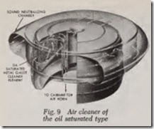
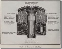
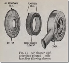
These devices, Figs. 9, 10, 11, are designed to separate dust and other foreign m atter from the incoming air before it enters the carburetor. Since thousands of cubic feet of air are drawn from within the hood of the car and passed through the engine cylinders, it is important that this air be clean. When driving along dusty roads, dust is drawn through the radiator and ultimately finds its way into the engine unless the air is filtered and cleaned. Foreign matter in the engine causes excessive wear and operating troubles.
In the type filter shown in Fig. 9, the filtering element is usually made from copper gauze or copper wool saturated with oil and packed into position between wire or other open-work sections of the cleaner body. Air entering the engine passes through the filtering element which traps the dust and air. The filter element should be washed in gasoline or kerosene at regular lubrication periods, or oftener if operating conditions warrant. After washing out the dirt and old oil, dip the filter element in clean engine oil, allowing the excess oil to drain before reassembling the filter.
The gauze or wool in the filter also acts as a Harne arrest er during tl. severe flashback or back fire. The filter shown in Fig. 9 contains a silencing unit consisting of intake passages designed to
muffie air noises.
The air cleaner shown in Fig. 10 is of the oil bath type. A cavity in the base of this cleaner contains a quantity of oil. The incoming air is forced to reverse its direction of flow immediately above the surface of the oil and the heavier parti cles of dust are carried into the oil by their momentum. The air then passes through an oil saturated copper gauze where the remaining dust is removed.
Fig. 11 illustrates a paper-element type of air cleaner £rst introduced on many 1957 cars. The air cleaner element is of the disposable dry type and consists of a cylindrical cellulose £ber ma terial, pleated to permit maximum £Iter area. On each end of this cylinder, the £ber is embedded in end plates to provide an efficient dust seal. On both sides of the £ber, rust resistant wire screen furnishes compressive strength. The £ne mesh of the inner screen also acts as a flame arrester in case of backfire.
The £ber of the element passes air through with low restriction, but any dust or dirt in the air deposits on the pleated outer surface. The fiber is flame-proofed and will retain its filtering efficiency under normal concentrations of gasoline vapor, engine oil and water vapor.
FUEL GAUGES
Automobiles are equipped with fuel gauges which are operated in conjunction with the ve hicle’s electrical system. The two types are the electric meter and rheostat type, and the bimetal and resistance wire type. The details of their operation are discussed in the Dash Gauges chapter.
FUEL LINES
Fuel lines connecting the various units of the fuel system are usually made of rolled steel and sometimes drawn copper. Steel tubing, when used for fuel lines, is generally rust proofed by being copper or zinc plated.
Fuel lines are placed away from exhaust pipes, muffiers and manifolds so that excessive heat will not cause vapor lock. They are attached to the frame, engine and other units so that the effect of vibration is minimized and so they are free of con tact with sharp edges which might cause wear. In places of excessive movement, as between the car’s frame and rubber-mounted engine, short lengths of gasoline resistant flexible tubing are used.
CARBURETOR
The carburetor is an instrument for metering fuel and air, and for atomizing and vaporizing the fuel charge. The Physics of Carburetion and How a Carburetor \Vorks are explained further on.
INTAKE MANIFOLDS
An intake manifold is a system of passages which conduct the fuel mixture from the carbure tor to the intake valves of the engine. Manifold design has a great deal to do with the efficient operation of an engine. For smooth and even operation, the fuel charge taken into each cylinder should be of the same strength and quality. The distribution of the fuel should, therefore, be as even as possible. This depends greatly on the design of the intake manifold. Dry fuel vapor is the ideal form of fuel charge but present-day fuel prevents this unless the mixture is subjected to high temperature. If the fuel charge is heated too highly, the power of the engine is reduced be cause the heat expands the fuel charge. Therefore, it is better to have some of the fuel deposited on the walls of the cylinders and manifold passages. Manifolds in modern engines are designed so that the amount of fuel condensing on the intake mani fold walls is reduced to a minimum.
The inside of the intake manifold is smooth and the passages are large enough so as not to obstruct the flow of the fuel mixture. The bends or curves in the manifold are designed so that a minimum amount of fuel will be condensed on the walls of the manifold.
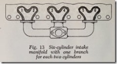
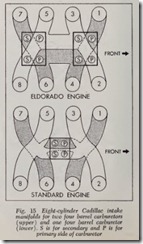
Figs. 12 to 15 illustrate the arrangement of in take manifolds for various type engines.
RAM INDUCTION MANIFOLDS
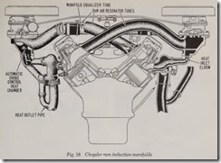
Available on some 1958-61 Chrysler engines, the system consists of twin air cleaners, twin four barrel carburetors and two manifolds containing eight long tubes of equal length (four for each manifold), Fig. 16.
The system is designed to increase power out put by 10 per cent in the middle speed range ( 1800-3600 rpm). Each manifold supplies one bank of cylinders and is carefully calculated to harness the natural supercharging effect of a ram induction system. By taking advantage of the pulsations in the air intake column caused by the valves opening and closing, sonic impulses help pack more mixture into the combustion chambers. A brief explanation of how this is accomplished follows:
In an engine with conventional manifolds, sev eral cylinders are supplied by one manifold with branches of varying lengths. The incoming fuel-air mixture does not have a smooth, steady flow into the combustion chambers; rather its behavior is erratic due to the inertia of the moving mixture and the opening and closing of the valves.Chrysler engineers, after much experimenting with the ram effect on engine induction systems, knew they could calculate effective intake tube lengths for various engine speeds, and the tubes could be placed between the carburetor and the intake ports, or extended from the conventionally mounted carburetor.
By using telescoping tubes and an engine dynamometer they found that with the carburetor mounted on the engine and the tubes extending from it the power increase obtained was in the 2400-4500 rpm range. But since most driving is done in the middle speed range ( 1800-3600 rpm) this would not do for passenger cars. Therefore, the carburetors were mounted to the sides of the engine with the tubes extending to the intake ports. Then, by trial and error, it was found that eight tubes, 30 inches long, would produce a steady power increase in the middle speed range. In other words, all the tubes were tuned to the same frequency which eliminated the power-rob bing pulsations in the power curve. An added ad vantage with this set-up is that the carburetors can be kept cooler while the engine is running, and can pick up less conducted heat from the engine when it is not running.
In the Chrysler system, the air-fuel mixture from each carburetor flows into a chamber di rectly below the carburetor, then passes through the long individual intake branches to the oppo site cylinder bank. The right-hand carburetor sup plies the air-fuel mixture for the left-hand cylinder bank, whereas the left-hand carburetor sup plies the right cylinder bank. The passages between the right- and left-hand manifolds are interconnected with a pressure equalizer tube to maintain balance of the engine pulsations.
MANIFOLD HEAT CONTROL
Most engines have automatically operated heat controls which utilize the exhaust gases of the engine to heat the incoming fuel-air charge during starting and warm-up so as to improve vaporiza tion and mixture distribution. The heat control is regulated by a coiled thermostatic spring mounted on the exhaust manifold, Fig. 17. A counterweight is mounted on the other end of the heat control valve shaft and this counterweight, in conjunction with the thermostatic spring, operates to close and open the heat control valve.
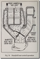
When the engine is cold, all of the exhaust gas is deflected to and around the intake manifold “hot spot,” Fig. 18. As the engine warms up, the thermostatic spring is heated and loses t ension, thereby permitting the counterweight to gradually change the position of the heat control valve so that at higher driving speeds with a thoroughly warmed engine, the exhaust gases are passed di rect to the exhaust pipe and muffier as shown by the dotted arrows.
Ram Induction Manifold
In the Chrysler ram induction system, there is a heat control chamber in each manifold to operate the automatic choke and to heat the fuel mixture after warm-up. A hear control valve in each ex haust manifold by-passes exhaust gas through an elbow to the intake manifold heat control cham ber. Heat outlet pipes then carry the gas down to a “Y” connector under the heat control valve.
EXHAUST SYSTEM
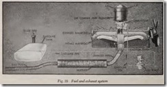
This system, when used on an “In-Line” engine, such as in Fig. 19, consists of an exhaust manifold, exhaust pipe, mufHer, and mufHer outlet (or tail) pipe. The burned gases from the engine are con ducted to the mufHer, and from there they are led from the mufHer outlet pipe to the atmosphere.
A mufHer quiets the noise of the exhaust by damping the sound waves created by the opening and closing of the exhaust valves. When an ex haust valve opens it discharges the burned gases at high pressure (around 75 pounds) into the exhaust pipe which is at low pressure (a little above atmospheric, 15 or 16 pounds). This action creates sound waves that travel through the flow ing gas, moving much faster than the gas itself, up to about 1400 m.p.h., that the mufHer must si lence. It does this principally by converting the sound wave energy to heat. This is usually ac complished by passing the exhaust gas, with its accompanying wave pattern, throughout perfo rated tubes into chambers of various sizes. Passage through the perforations and subsequent reflec tion within the chamber forces the sound waves to dissipate their energy. Hereafter, the sound wave pattern and gas How will be treated as one in describing the various types of muffiers.
The mufHer shown in Fig. 20 operates on the reverse How principle. It is oval-shaped and has multiple pipes. Four chambers and a double acket are utilized to accomplish muffiing of exhaust noise. Exhaust gases are directed to the third chamber, forced forward to the first cham ber, from where they travel the length of the muffier and are exhausted into the tail pipe. Ar rows in picture show direction of gas How.
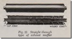
Fig. 21 shows a straight through type muffier. This mufHer is provided with a central tube, per forated with many openings which lead into an outside chamber packed with a sound absorbing (insulating) material. As the exhaust gases expand through the perforated inner pipe into the outer chamber, they come in contact with the in sulator and escape to the atmosphere under a con stant pressure. In this manner the expanding chamber tends to equalize or spread out the pres sure peaks of the exhaust from each individual cylinder of the engine.
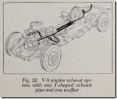
Engines of the V-8 type require two exhaust manifolds and either one or two muffiers and often accompanying resonators. If one mufHer is used, the exhaust pipe from one manifold meets the other one in the form of a “Y”, Fig. 22.
DUAL EXHAUST SYSTEM
Two types of dual exhaust systems are shown in Figs. 23 and 24. Each exhaust manifold connects to a separate exhaust pipe, muffier and tail pipe. The resonators shown in Fig. 24 can be considered as being additional muffiers as they are used to reduce exhaust noise further.
The advantage of a dual exhaust system is that the engine exhausts more freely, thereby lowering the back pressure which is inherent in an exhaust system. With a dual exhaust system a sizeable in
crease in engine horsepower can be obtained be cause the “breathing” capacity of the engine is improved, thereby leaving less exhaust gases in the engine at the end of each exhaust stroke, which leaves more room for an extra intake of the air-fuel mixture.





![Fig. 23 Dual exhaust system_thumb[1] Fig. 23 Dual exhaust system_thumb[1]](http://machineryequipmentonline.com/electric-equipment/wp-content/uploads/2020/06/Fig.-23-Dual-exhaust-system_thumb1_thumb.jpg)
