Equations (13.30) may be transformed by changing the variables through currents elimination.
−1Ψs −Ψr Lm ; σ =1- Lm2
Ls L Ls r L Ls r (13.54)
![]() ir = σ−1Ψr −Ψs Lm Lr L Ls r
ir = σ−1Ψr −Ψs Lm Lr L Ls r
(13.55)
with
Ks = LLms ; Kr = LLmr
|
τ =s ‘ τ ⋅σs ; τ =r ‘ τ ⋅σr τ =s RLss ; τ =r RLrr |
(13.56) |
By electrical transients we mean constant speed transients. So both ωb and ωr are considered known. The inputs are the two voltage space phasors Vs and Vr and the outputs are the two flux linkage space phasors, Ψs and Ψr .
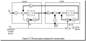
The structural diagram of Equations (13.55) is shown in Figure 13.7. The transient behavior of stator and rotor flux linkages as complex variables, at constant speed ωb and ωr, for standard step or sinusoidal voltages
Vs , Vr signals has analytical solutions. Finally, the torque transients also have analytical solutions as
The two complex eigenvalues of (13.55) are obtained from
![]() τs ‘p+ + ω τ−1Ksj b s ‘ τr ‘p+ +1 −j(Kω −ω τrb r ) r’
τs ‘p+ + ω τ−1Ksj b s ‘ τr ‘p+ +1 −j(Kω −ω τrb r ) r’![]() = 0 (13.58)
= 0 (13.58)
As expected, the eigenvalues p1,2 depend on the speed of the motor and on the speed of the reference system ωb. Equation (13.58) may be put in the form
+p2(τ τ +1s+’ jr⋅ω ⋅τ’ pb[(τ +τss” 1r ‘)+ τ τj s ‘ r ‘ 2( ω −ωb r )]−K Ks r + (13.58’) )( + j⋅ ω −ω ⋅τ( b r ) r ‘)= 0
In essence, in-rush current and torque (at zero speed), for example, has a rather straightforward solution through the knowledge of eigenvalues, with ωr = 0 = ωb.
p2τ τ + τ +τ −s ‘ r ‘ p( s ‘ r ‘) K Ks r + =1 0
![]() (p1,2 )ω =ω =r b 0 = − τ +τ( s ‘ r ‘)± (τ +τs ‘ 2rτ τ‘)s2‘ − τ τr ‘4 s ‘ r ‘(−K Ks r +1) (13.59)
(p1,2 )ω =ω =r b 0 = − τ +τ( s ‘ r ‘)± (τ +τs ‘ 2rτ τ‘)s2‘ − τ τr ‘4 s ‘ r ‘(−K Ks r +1) (13.59)
The same capability of yielding analytical solutions for transients is claimed by the spiral vector theory. [5]
For constant amplitude stator or rotor flux conditions
![]()
![]()
![]() ddtΨs = j(ω −ω Ψ1 b ) s or ddtΨr = j(ω −ω Ψ1 b ) r ; ω −1 stator frequency
ddtΨs = j(ω −ω Ψ1 b ) s or ddtΨr = j(ω −ω Ψ1 b ) r ; ω −1 stator frequency
Equations (13.55) are left with only one complex eigenvalue. Even a simpler analytical solution for electrical transients is feasible for constant stator and rotor flux conditions, so typical in fast response modern vector control drives. Also, at least at zero speed, the eigenvalue with voltage supply is about the same for stator or for rotor supply.
![]() The same equations may be expressed with is and Ψr as variables, by simply putting a = Lm/Lr and by eliminating ir from (13.51) with (13.50).
The same equations may be expressed with is and Ψr as variables, by simply putting a = Lm/Lr and by eliminating ir from (13.51) with (13.50).
INCLUDING MAGNETIC SATURATION IN THE SPACE PHASOR MODEL
To incorporate magnetic saturation easily into the space phasor model (13.49), we separate the leakage saturation from main flux path saturation with pertinent functions obtained a priori from tests or from field solutions (FEM).
![clip_image007[4] clip_image007[4]](http://machineryequipmentonline.com/electric-equipment/wp-content/uploads/2017/04/clip_image0074_thumb1.gif)
![]() Lsl = Lsl (i , Ls ) lr = Llr (i ; r ) Ψm = Lm (im ) im (13.60)
Lsl = Lsl (i , Ls ) lr = Llr (i ; r ) Ψm = Lm (im ) im (13.60)
im = is +ir (13.61)
![]()
![]() Let us consider the reference system oriented along the main flux Ψm , that is, Ψm = Ψm , and eliminate the rotor current, maintaining Ψm and is as variables.
Let us consider the reference system oriented along the main flux Ψm , that is, Ψm = Ψm , and eliminate the rotor current, maintaining Ψm and is as variables.
![]() Vs = [Rs +(p + ωj b )Lsl (is )]⋅is +(p+ ωj b )⋅Ψm
Vs = [Rs +(p + ωj b )Lsl (is )]⋅is +(p+ ωj b )⋅Ψm
Vr = Rr +(p + j(ω −ωb r ))Llr im −is ⋅ im −is +(p + j(ω −ωb r ))⋅Ψm
Ψm (13.63) im = Lm ( )im
We may add the equation of motion,
![]() JpPω1 r = 23 p Real j1 ( Ψmis* )−Tload (13.64)
JpPω1 r = 23 p Real j1 ( Ψmis* )−Tload (13.64)
Provided the magnetization curves Lsl(is), Llr(ir) are known, Equations (13.62)–(13.64) may be solved only by numerical methods after splitting Equations (13.62) along d and q axis.
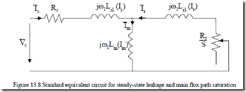
For steady-state, however, it suffices that in the equivalent circuits, Lm is made a function of im, Lsl of is0 and Llr(iro) (Figure 13.8). This is only in synchronous coordinates where steady-state means dc variables.
In reality, both in the stator and rotor, the magnetic fields are a.c. at frequency ω1 and Sω1. So, in fact, in Figure 13.8, the transient (a.c.), inductances should be used.
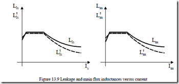
Llst ( )is = Lls( )is + ∂∂Lisls is < Lls( )is
Llrt ( )ir = Llr ( )ir + ∂∂Lirlr ir < Llr ( )ir (13.65)
Lmt ( )im = Lm ( )im + ∂∂Limm im < Lm ( )im
Typical curves are shown in Figure 13.9.
As the transient (a.c.) inductances are even smaller than the normal (d.c.) inductances, the machine behavior at high currents is expected to show further increased currents.
Furthermore, as shown in Chapter 6, the leakage flux circumferential flux lines at high currents influence the main (radial) flux and contribute to the resultant flux in the machine core. The saturation in the stator is given by the stator flux Ψs and in the rotor by the rotor flux for high levels of currents.
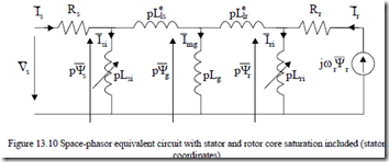
So, for large currents, it seems more appropriate to use the equivalent circuit with stator and rotor flux shown (Figure 13.10). However, two new variable inductances, Lsi and Lri, are added. Lg refers only to the airgap only. Finally the stator and rotor leakage inductances are related only to end connections and slot volume: Llse, Llre. [6]
As expected, the functions Ψs(isi) = Lsiisi and Ψr(iri) = Lriiri have to be known together with Llse, Llre, Rs, Rr, Lg which are hereby considered constant. In the presence of skin effect, Llre and Rr are functions of slip frequency ωsr = ω1 – ωr. Furthermore we should notice that it is not easy to measure all parameters in the equivalent circuit on Figure 13.10. It is, however, possible to calculate them either by sophisticated analytical or through FEM models. Depending on the machine design and load, the relative importance of the two variable inductances Lsi and Lri may be notable or negligible.
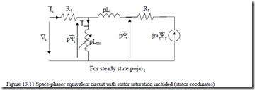
Consequently, the equivalent circuit may be simplified. For example, for heavy loads the rotor saturation may be ignored and thus only Lsi remains. Then Lsi and Lg in parallel may be lumped into an equivalent variable inductance Lms and Llse and Llre into the total constant leakage inductance of the machine Ll. Then the equivalent circuit of Figure 13.10 degenerates into the one of Figure 13.11.
When high currents occur, during transients in electric drives, the equivalent circuit of Figure 13.11 indicates severe saturation while the conventional circuit (Figure 13.8) indicates moderate saturation of the main path flux and some saturation of the stator leakage path.
So when high current (torque) transients occur, the real machine, due to the Lms reduction, produces torque performance quite different from the predictions by the conventional equivalent circuit (Figure 13.8), up to 2 to 2.5 p.u. current, however, the differences between the two models are negligible.
In IMs designed for extreme saturation conditions (minimum weight), models like that in Figure 13.10 have to be used, unless FEM is applied.


