ROCHESTER 2GC OVERHAUL
Adjustments on Car
Automatic Choke-Choke cover setting is indi cated by the index markings on the housing and air horn casting. With choke cover set in this position, choke valve should be just closed at 75 degrees F. ( engine and carburetor must be cooled down to room temperatur e ).
Fast Idle Cam Index-No adjustment of fast idle speed is provided since the steps on the fast idle cam are correctly proportioned to give the correct speed stops above normal idle speed. It is necessary, however, to have the correct relation ship between fast idle cam position and choke valve position. To check and adjust the settin g, proceed as follows:
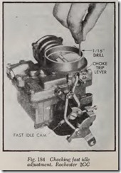
Place end of idle screw on next to highest step on fast idle cam, Fig. 184. A 1/16″ drill should slide easily between upper edge of choke valve and bore of carburetor as shown. If necessary, bend choke trip lever tang until prescribed clear ance is obtained.
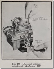
Unloader-Place throttle in wide open position. Large end of tool shown in Fig. 185 should slide freely between upper edge of choke valve and bore of carburetor. If necessary, bend tang of throttle lever with tool shown in Fig. 186 to obtain the necessary clearance.
Carburetor Disassemble
Flooding, stumbling on acceleration and other performance complaints are in many instances caused by the presence of dirt, water or other foreign matter in the carburetor. To aid in diag nosing the cause of the complaint, th e carburetor should be carefully removed from the engine without draining th e fuel from the bowl. The contents of the fuel bowl m ay then be examin ed for contamination as the carburetor is disas sembled.
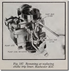
Bowl Cover-Remove the three attaching screws and remove the choke cover and coil as sembly. Remove choke cover gasket and baffie plate. Remove retaining screw at end of choke shaft, Fig. 187, and carefully pry on choke trip lever, fast idle link and lever. Lever can be re moved from link by turning until slot in lever will pass over tang in link. Rotate link until it will slip out through slot in fast idle cam.
Remove fuel filter. Remove filter screen retainer nut and gasket with %” wrench and remove screen. Disconnect pump link from throttle lever by removing retainer. Link can be removed com pletely by rotating until it clears pump lever, Fig.187. Remove eight screws and lift cover from bowl, Fig. 188.
Remove two screws and take out choke valve. Rotate choke shaft counterclockwise to free choke piston from housing, then pull piston and choke shaft from carburetor, Fig. 189. Remove two screws and take off choke housing and gasket.
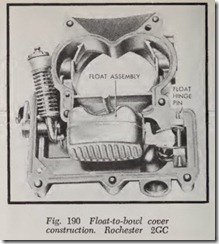
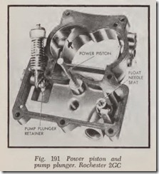
Place up-ended cover on flat surface. Remove float hinge pin and lift float assembly from cover, Fig. 190. Float needle may now be removed from float. Remove float needle seat and gasket With wide blade screwdriver. Remove power piston, Fig. 191. Remove retainer on pump plunger shaft and plunger assembly from pump arm, Fig. 191. The pump lever and shaft may be removed by loosening set screw on inner arm and removing outer lever and shaft. The pump plunger may be further disassembled by compressing the spring and removing the retainer.
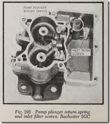
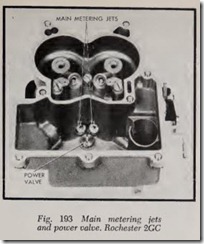
Disassemble Bowl-Remove pump inlet filter screen and pump plunger return spring. Remove check ball from bottom of pump well, Fig. 192. Remove main metering jets and power valve, Fig.193. Remove three screws on top of cluster and lift out cluster and gasket.
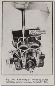
Using long-nose pliers, Fig. 194, remove pump discharge spring retainer. Then remove the spring and check ball.
Invert carburetor and remove three large bowl to-throttle body attaching screws, and remove throttle body and gasket. Remove fast idle cam.
Remove idle adjusting needles and springs from throttle body, and the idle screw from throttle lever.
Cleaning and Inspection
1. Thoroughly clean carburetor castings and metal parts in cleaning solvent. Choke coil and housing, and pump plunger should not be immersed in solvent. Use clean gasoline only on pump plunger.
2. To avoid damage to gasket between choke housing and air hom do not soak air horn in cleaner or solvent if choke piston housing has not been removed.
3. Check float needle and seat for wear. If wear is noted the assembly must be replaced.
4. Check float lip for wear and float for dents.
Check floats for leaks by shaking.
5. Check throttle and choke shaft bores in throttle body and cover castings for wear or out-of-round condition.
6. Inspect idle adjusting needles for burrs or ridges. Such a condition requires replacement.
7. If wear is noted on steps of fast idle cam, it should be replaced as it may upset engine idle speed during the warm up.
8. Inspect pump plunger leather. Replace plunger if leather is damaged.
9. Check both filter screens for dirt or lint. Clean them and if they are distorted or remain plugged, replace.
10. If for any reason parts have become loose or damaged in the cluster casting, it must be re placed.
Carburetor Assemble
Throttle Body-Install idle screw in throttle lever. Screw idle adjusting needles and springs into throttle body until finger tight. Back out screws m turns as a preliminary idle adjustment. Place new throttle body gasket in position and attach throttle body. Tighten screws evenly and securely.
Bowl Assemble-Install fast idle cam. Drop pump discharge check ball (steel) into discharge hole and replace spring and retainer, Fig. 194. Replace cluster and gasket, tightening screws evenly and securely. Make certain center screw is fitted with gasket to prevent pump discharge leakage.
Replace main metering jets and power valve, Fig. 193. Drop pump inlet ball check into hole in pump well (ball is aluminum). Install pump re turn spring, pressing it with finger to center it in pump well. Replace pump inlet strainer, pressing carefully into position.
Bowl Cover Assemble-Place new gasket into position and attach choke housing to air horn. Tighten screws securely. Assemble choke piston to shaft with pin, with :B.at cut side of piston toward air horn, Fig. 189. Place shaft in choke housing and rotate clockwise so that piston slides in hous ing. Install choke valve on choke shaft with letters “RP” facing upward. Center choke valve before tightening screws. (While centering choke valve, install fast idle lever, choke trip lever and tighten attaching screws temporarily.)
Replace pump lever assembly. Install :B.oat needle seat and gasket, using wide blade screw driver. Place power piston in vacuum cavity, be ing sure piston travels freely in cavity, Fig. 191. Attach plunger shaft with retainer, with shaft end pointing inward. Install cover gasket. Attach needle to :B.oat, carefully position :B.oat and insert hinge pin, Fig. 190.
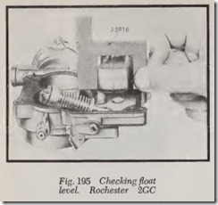
Float Adjustments- To adjust :B.oat level, place :B.oat gauge, Fig. 195, in position over :B.oat and resting on gasket surface. Highest point of :B.oat should just touch gauge. Adjust by bending :B.oat arm. Measurement from gasket surface to high point of :B.oat is’ 115/64.”
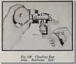
Check and adjust :B.oat drop. With air horn right side up so that :B.oat can hang free, the distance from the gasket surface to the lowest point of the :B.oat should be 1 29/32″ and can be measured with :B.oat gauge shown in Fig. 196. To adjust, bend :B.oat tang.
Final Assembly-Place cover on bowl, making certain that accelerator pump plunger is correctly positioned and will move freely, Fig. 188. Install and tighten 8 cover screws evenly and securely. Install filter screen with closed end toward air horn. Install strainer nut and gasket in cover.
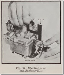
Install pump link and retainer, Fig. 186. To adjust pump link, place float and pump gauge on air horn next to air intake with single leg of gauge downward toward pump link, Fig. 197. With throttle stop screw backed off so that throttle valves are tightly closed, the top surface of the pump rod should just touch the end of the gauge. The measurement is .922.”
Place baffle plate and choke housing gasket into position and install choke coil and cover. Rotate cover counterclockwise until index marks on cover and housing are aligned. Attach three retainers and screws to choke housing and tighten securely.
Place link on fast idle cam and choke lever.
Place choke lever on cover with tang facing out ward and toward pump lever. Install spacer washer and trip lever so that tang of trip lever is under tang of choke lever, and install retaining screw, Fig. 187.
Complete the job by adjusting the fast idle and choke unloader as directed under Adjustments.
