Industrial Control
How to Automate: Monitor, Process, and Control
In this Chapter:
● Control defined.
● Open and closed control systems.
● Sensors and transducers.
● Actuators like relays, solenoids, and motors.
● Thyristors.
● Programmable logic controllers.
INTRODUCTION
Industrial control is one of the four major applications of electronics. In industrial control, electronic components, circuits, and equipment are used to operate various types of machines in manufacturing plants. Most industrial machines like robots are mechanical in nature but electrically operated. Most are powered by electric motors or other actuators. To operate the machine, electrical power must be properly controlled. Industrial control electronics is used to turn machines off and on at the appropriate time, control their speed of operation, and otherwise produce the desired manipulations.
Electronic control is not confined to industry. There is lots going on in the home and car as well. The principles given here apply to those applications as well.
OPEN- AND CLOSED-LOOP CONTROL
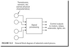
The basic industrial control process is illustrated in Figure 12.1. Electrical inputs, such as switches, sensors, or other devices, are used to initiate an elec- tronic control process. The signal-processing circuits generate control output signals that are used to operate the industrial machines. This basic process is known as open-loop control. The typical device being controlled by the output signals is an electric motor that operates a machine. Other outputs could oper- ate lights, relays, solenoids, or a variety of other devices.
Open-Loop Control
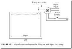
A simple example of an open-loop control system is shown in Figure 12.2. The input is a switch that applies electrical power to a motor. The motor, in turn, operates a pump that causes liquid to be put into a vat or tank. As soon as the vat is full, the operator turns the switch off. The basic control process in this system is simply turning power off and on to control the pump. The operator visually monitors the level in the vat until the correct level is reached.
Closed-Loop Control
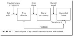
An improved form of industrial control system is illustrated in Figure 12.3 . It is known as a closed-loop control system. The system is given an initial input
reference called the set point. The set point is usually a voltage that represents some physical value that is to be achieved. It is applied to an error detector that compares this input to a signal from the controlled devices. If the two signals are different, an error output is produced. This error signal is processed (usu- ally amplified), and an output control signal is derived from it. It is this output signal that operates the controlled device. A transducer monitors the control- led device to see that the desired outcome is obtained. The signal from this transducer is called feedback. The feedback signal is compared to the input to produce the error signal. The control signal operates the controlled device until the error is reduced to zero. At that time, the desired output condition, where the feedback equals the set point, is obtained.
The key to closed-loop control is the feedback. Feedback signals tell the system whether the machine is performing correctly. The feedback signal allows the system to adjust itself in such a way that the desired output is con- tinuously accomplished. Control is automatic.
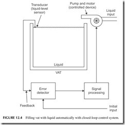
A closed-loop version of our system to fill a vat with liquid is shown in Figure 12.4. An initial input signal is applied to start the process. If the vat is not full, the transducer will sense it and send a signal to the error detector that says the liquid level is low. The error detector generates an output signal that is processed and used to start the pump motor. The motor rotates the pump, which puts liquid in the tank. When the vat is full, the sensor will generate a signal that is sent to the error detector. The error is now zero, so the pump motor is turned off.
The primary benefit of a closed-loop control system is that its operation is automatic. In the open-loop system, an operator has to turn the system off and on manually to fill the tank. In the closed-loop control system, the operator gives an initial input, called the set point, to which the error detector will com- pare the feedback signal from the sensor. He or she turns the system on. From that point on, operation is automatic. The pump turns itself off when the vat is full. If the liquid level drops below the desired level due to usage, the sensor indicates a low level and automatically turns on the motor so that the pump will again fill the tank. When the tank is full, the unit shuts off by itself.
Most industrial control systems are closed loop to make them automatic. And your home has some as well. Your toilet flusher is a closed loop as is your heating and air conditioning (HVAC) thermostat. Appliances like your washer, dryer, and dishwasher are other examples of closed-loop control. All of them contain a microcontroller with sensors, timers, and feedback to make them totally automatic.
Controllers
While many industrial control applications are implemented with simple con- trol circuits, most industrial control is carried out by specialized instruments called controllers. These units accept inputs from sensors, condition them, process them, and then generate output control signals.
A good example of an analog controller is one used to control the tem- perature in a system. A resistive temperature sensor is used to monitor the temperature of the liquid in a pipe. If the temperature goes up, the sensor out- put goes up. This is sensed by the controller circuitry. Inside the controller, a comparator is set to a desired temperature threshold. Should the temperature exceed a specified set point, the controller will turn off the device heating the
pipe and liquid. Should the temperature drop below another set point tempera- ture, the controller will turn on the heating device in an effort to maintain the set point temperature. While the heating element will be turning off and on, it will produce the desired average overall temperature.
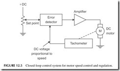
A continuous analog controller will provide proportional control rather than an off/off response. For instance, suppose that you want to control the speed of a motor. The system depicted in Figure 12.5 does this. You want the motor to stay set to the speed you want, say 1200 rpm. A pot connected to a voltage repre- sents that speed value. The voltage is applied to an error detector along with the feedback input from a tachometer. A tachometer is a device that senses rotational speed and develops a proportional DC voltage. That voltage is sent to the error detector and compared to the set point. If they are different, an error voltage is developed. This voltage is then amplified and applied to the motor. The speed of a DC motor is proportional to the voltage applied to it. So if the motor slows down, the error voltage is increased and that is amplified and applied to the motor speed- ing it up to compensate for the speed drop. A speed up in the motor produces an increased tachometer output. The resulting error signal causes the motor speed to drop until the error is zero. With such a circuit, the motor speed remains constant.
An analog controller is a product made up of the set point pot, error detec- tor, and a selection of amplifiers whose gain can be varied and an output amplifier that can drive the motor or other device. Many different types of commercial electronic controllers have been developed to monitor and control physical characteristics such as pressure, physical strain, weight, liquid flow rate, physical position, or liquid level in a tank. Digital controllers that contain a microcomputer are also available.
SENSORS
An essential element of most control systems is the inputs from sensors. Sensors are the components that detect physical changes or events and convert them into
electrical signals to be processed. Sometimes the term transducer is used to refer to the sensor. A transducer is a device that converts one type of energy into another such as mechanical energy to electrical. There are literally hundreds of different types of sensors. A few examples of the most common types follow.
Temperature Sensors
Temperature is probably the most often sensed physical characteristic. Temper- ature sensors convert temperature to a resistance change or voltage change. The most commonly used temperature sensors are RTDs, thermistors, and thermocouples.
RTD—An RTD is a resistive temperature device. It is essentially just a platinum wire whose resistance varies with temperature. Most of them have a resistance of 100 ohms at zero degrees Celsius (0°C). As the temperature changes, the resistance changes to reflect the change. RTDs have what we call a linear positive temperature coefficient. That is, as the temperature goes up the resistance goes up and vice versa.
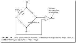
To convert the resistance variation into a voltage, the RTD is usually put into a bridge circuit as shown in Figure 12.6. The bridge is initially balanced with the variable calibrate control (CAL) to produce zero output at a given temperature. Then if the temperature varies, the bridge becomes unbalanced and a voltage is produced. This is then amplified into a larger voltage that is a measure of the temperature. The output can be measured with a meter or it can be digitized for use as in input to a digital system for display or control.
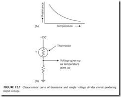
Thermistor—A thermistor is a resistor whose resistance has a negative temperature coefficient. As temperature goes up the resistance goes down and vice versa (see Figure 12.7A ). The resistance change is much greater than that
of an RTD. The thermistor can be used in a simple voltage divider to develop an output voltage or in a bridge circuit like the RTD (see Figure 12.7B).
Thermocouple—A thermocouple is a unique type of temperature sensor, as it develops a voltage rather than a resistance change. It is formed with two dissimilar metals. If the junction of the metals is heated, a voltage is devel- oped. The voltage is usually in the millivolt range so that it usually has to be amplified before it becomes useful. The thermocouple’s main advantage is its accuracy at very high temperatures.
Solid State—Diodes and transistors make good temperature sensors. A silicon diode has a very linear voltage drop variation that decreases with an increase in temperature. This is true of the emitter-base junction of a bipolar transistor as well. Zener regulator diodes exhibit a similar response. The sen- sor is usually packaged into a complete integrated circuit with an amplifier that produces a voltage output proportional to the temperature variation.
Pressure Sensors
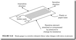
A pressure sensor responds to force or pressure. There are many different types. A widely used kind is called a strain gauge. A strain gauge is essentially a thin pattern of metal deposited on a plastic base like that shown in Figure 12.8. It has a specific value of resistance. A value of 120 ohms is common. The strain
gauge is then glued or cemented with an adhesive to the object to which the pressure is to be applied. An example is a steel beam. When pressure is applied to the beam, it will bend. As it bends, it stretches or compresses the strain gauge resistance element. If the resistive element is stretched, its resistance increases. If it is compressed the resistance decreases. Knowing the specific character- istics of the resistance change per pound of pressure, an exact measure of the pressure can be determined. Mostly strain gauges are used in a bridge circuit like that shown in Figure 12.6. Since the resistance variation is small and the resulting bridge circuit output is small, a special amplifier called an instrumen- tation amplifier is used. It has differential inputs and very high gain.
A special pressure sensor called a load cell is typically made up of strain gauges. It is fully calibrated to provide a specific voltage output with a specific pressure. Load cells are widely used for weight measurement. An example application is the use of load cells in truck weighing scales.
There are other forms of pressure transducers. Many are solid-state devices with an output voltage proportional to pressure. Piezoelectric pressure trans- ducers use the voltage produced by certain types of crystals or ceramics when pressure is applied to them.
Switches
Switches are widely used as sensors. Switches are mechanical devices with electrical contacts that open or close with a particular physical movement. Switches are used to detect mechanical movement and specifically to deter- mine when the limit of some physical device has been reached. Called limit switches, these devices have various arms and mechanisms that permit ease of use in a variety of situations. Examples of such switches are those that can detect when a cabinet door is open or closed or a switch that senses when a mechanical device reaches a specific point where motion must be stopped.
And of course, a human-operated switch may be the most common. It is usu- ally a button that is pushed to initiate or stop some action.
Potentiometers
A potentiometer is a variable resistor or variable voltage divider. While most electronic pots are rotary devices, they also come in a linear variety. The vari- able arm of the pot is controlled by some external mechanical device. Then by using the resistance value of the pot or the voltage it produces as a variable voltage divider, it can be used to sense mechanical position.
Photoelectric Sensors
One of the most widely used industrial transducers is a photoelectric sensor. A photoelectric sensor is a component that responds to light and produces an electrical signal that can initiate some operation.
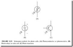
There are three basic types of photoelectric sensors. These are the photo- resistive or photoconductive cell, the photovoltaic cell, and the phototransistor. The photoconductive sensor is a light-sensitive resistor. Its schematic symbol is shown in Figure 12.9A. The resistance of the device varies with the amount of light falling on it. With no light falling on the sensor, its resistance will be very high, 100,000 ohms or more. When bright light shines on the sensor, how- ever, its resistance will drop to a very low value, usually several hundred ohms or less. Of course, at a light level between bright and dark, the resistance of the device will be somewhere between 100 ohms and several hundred thousand ohms. The resistance is inversely proportional to the light level.
Another type of photoelectric device is the photovoltaic cell, whose sche- matic symbol is illustrated in Figure 12.9B. This is the solar cell described in an earlier chapter. Whenever bright light falls on the cell, it will generate a small DC voltage. The maximum output of a typical photovoltaic cell is approx- imately 0.45 to 0.5 volt. At lower light levels, the output voltage will be less. Photovoltaic cells are used primarily in power generation systems for produc- ing charging voltage for batteries in satellites and other remote systems. Multiple cells are connected in various series and parallel combinations to get the desired voltage level and current capacity. In some applications, the photovoltaic cell can be used for industrial control. These are also found in portable calculators. Two AA cells at 1.5 volts each produce 3 volts in series. To generate 3 volts with 0.5- volt solar cells, you would need to connect six in series (6 X 0.5 = 3 volts).
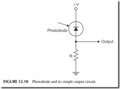
A silicon diode can also be used as a light detector. Special diodes in clear housings are often used to detect light. These are called photodi- odes. Photodiodes are operated in the reverse-biased direction, as shown in Figure 12.10. With no light falling on the diode, it is cut off, so there is no voltage across R1. When light strikes the diode, its reverse leakage current increases dramatically, causing a voltage drop to occur across R1.
A phototransistor is a light-sensitive transistor. Its symbol is given in Figure 12.9C. It only has two terminals, the emitter and the collector. The device has a base, but typically it has no lead. Instead, the device is built so that when the base is exposed to light, it will cause the emitter-base junction to conduct. When light strikes the base, it causes ionization, which simulates base-current flow. Therefore, the transistor conducts between emitter and collector. The pri- mary advantage of a phototransistor is its very high sensitivity over a photo- diode. It will conduct even with a small amount of light applied to the base. The transistor essentially provides amplification so that small light levels can control a large current.
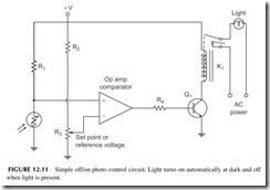
A typical closed-loop control circuit using a photoelectric cell is illustrated in Figure 12.11. This circuit will automatically turn a light on when it gets dark and turn the light off when it is light again. Note that a photoresistive cell is connected as part of a voltage divider with resistor R1. The DC voltage from this voltage divider is applied to one input of an op amp comparator. The DC reference input to the comparator comes from a voltage divider made up of R2 and R3. The potentiometer can be used to adjust the DC reference voltage or set point. The output of the comparator drives a switching transistor Q1, which will turn the relay K1 off or on. This, in turn, operates the light.
When the photoresistive cell is exposed to light, its resistance will be very low. Therefore, the voltage from the voltage divider will be low. It will be less than the DC set point voltage and the comparator will not be triggered. The output of the comparator will be a negative voltage, which will reverse bias the emitter-base junction of the transistor and keep it turned off. As soon as it gets dark outside, the resistance of the photocell will increase. This will cause the voltage-divider output to increase. At some point, the voltage will be higher than the set point voltage, causing the comparator to switch. This applies a positive voltage to the transistor base, turning it on, and then turning on the relay and the light. The light will remain on as long as the photoconductive cell is in the dark. But as soon as light shines on the photocell, the voltage- divider output voltage will drop, thereby triggering the comparator and turning off the transistor, the relay, and the light bulb. By adjusting the reference or set point voltage with potentiometer R3, the triggering point can be varied, so that the light will be turned off or on at the desired level of ambient lighting.
This same basic concept can be used to produce a variety of industrial con- trol operations. For example, you could use the circuit as an entry or intru- sion detector. Shine a light on the photocell. If someone or something comes between the light and photocell, the circuit will trigger and the relay could then be used to operate a bell or buzzer or light.
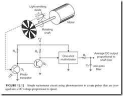
Another example of a photoelectric controller is a tachometer circuit used for measuring the speed of a rotating shaft. Figure 12.12 shows a small, plastic wheel connected to the shaft of a motor. There are alternate clear and opaque areas on the disk. The disk is positioned so that it is between the light-emitting diode (LED) and the phototransistor. As the disk rotates, the dark opaque areas will block the light, while the clear areas pass the light from the LED to the phototransistor. When a clear area on the disk passes, the LED light will shine through it, hitting the phototransistor, and turning it on. When a dark area passes, the light will be blocked and the phototransistor will turn off. The rapidly rotating disk will cause the transistors to turn off and on very rapidly. This rapid conduction and nonconduction of the phototransistor causes a series of pulses to occur at the output of Q2. These pulses are used to trigger the one- shot multivibrator.
The one-shot multivibrator produces a series of fixed, amplitude-width pulses. These are applied to an RC low-pass filter made up of C1 and R1. This filter will average the pulses into a DC voltage. This output voltage is propor- tional to the motor speed. If the speed of the motor should increase, the pulses
occur at a more rapid rate. This means that the pulses occur closer together, and thus the average voltage across C1 goes up. A DC voltmeter connected to the output can be used to indicate the speed. At low speeds, the meter indica- tion will be low, while at high speeds it will be high. The meter dial itself can be calibrated in terms of revolutions per minute (rpm), thereby giving an accu- rate speed indication.
Flow Sensors
These devices have liquid or gas pass through them and measure the amount of flow in gallons per minute or other measure. They develop an output volt- age proportional to flow rate.
There too many other sensors to catalog here but in most cases there is a sensor to convert any physical variable into a voltage to be measured.
OUTPUT DEVICES
An output device or an actuator is the thing that is most often controlled in a control system. The two most common types of actuators are relays and motors. There are many types of both.
Relays
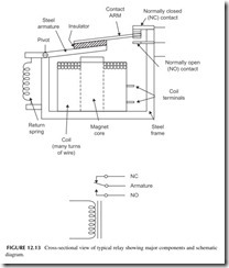
A relay is an electromagnetically operated switch. A typical relay, and its sche- matic symbol, is illustrated in Figure 12.13. Its main components are a mag- netic coil and a set of switching contacts. With no current applied to the coil, the spring keeps the armature pulled down, so that the contact arm makes con- nection with the upper, normally closed (NC) contact. When current is applied to the coil, a magnetic field is produced. This magnetic field attracts the steel armature, opening the upper contact, and closing the lower, normally open (NO) contact. The contacts form a single-pole, double-throw (SPDT) switch. When power is disconnected from the coil, the magnetic field ceases, and the contacts return to their initial state because of the spring.
Relay coils are designed to be operated from either AC or DC. The con- tacts are small circular disks of silver or tungsten. These materials are cho- sen because they will handle a large amount of current with minimum burning, arcing, and pitting.
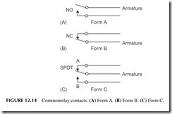
The various kinds of switching contacts used in relays are illustrated in Figure 12.14. Normally open (NO) contacts are referred to as form A. Applying power to the coil closes the contacts. Normally closed (NC) contacts are refer- red to as form B. When power is applied to the relay coil, the contacts open. Single-pole, double-throw switching contacts are referred to as form C. When power is applied to the relay coil, the contact arm moves from contact A to contact B. Form C contacts are usually of the break-before-make variety. That is, contact A opens before the arm touches or “makes” contact B.
Sometimes you will hear the expression that a relay has been “picked” or “picked up.” This means that power has been applied to the relay coil, and its contacts have been moved according to their function, and switching of a cir- cuit has occurred.
Most relays usually have more than one set of contacts, so that multiple switching operations can be performed simultaneously. The various contact arms are ganged together so that they operate together when power is applied to the coil. A common configuration is two form-A contacts ganged to form a double-pole, single-throw (DPST) relay. Putting two form-C contacts together on the same relay produces a double-pole, double-throw (DPDT) relay.
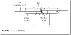
Another widely used type of relay is the reed relay, illustrated in Figure 12.15. The heart of the reed relay is a reed switch that consists of two thin, metallic, reed contacts sealed in a glass tube. The reed contacts are made of a magnetic material, so that they will be magnetized when a magnetic field is applied to them. A coil consisting of many turns of fine wire is wound on a form and placed over the reed switch. When power is applied to the coil, a magnetic field is produced. This magnetic field magnetizes the two reeds as if they were bar magnets. One end of each reed will have a north pole and a south pole. The reeds are positioned so that the north pole of one will attract the south pole of the other. Remember, magnetic theory says that unlike poles attract, while like poles repel. The result is that the contacts will move toward one another and touch, making a good electrical connection. When power is removed from the coil, the contacts become demagnetized and spring apart. The reed relay will also operate by moving a permanent magnet near it. When the magnet is near, the contacts will close. This is a common way to sense open windows or doors in a home security system.
The contacts on reed relays cannot handle as much power as the contacts on conventional relays because they are smaller. As a result, they are used only in lower current power applications. However, the contacts on a reed relay open and close faster than those of a larger standard relay. Reed relay con- tacts can open and close in a few hundred microseconds, while standard relays require many milliseconds to open or close because of the larger contacts and the related structures that must be moved.
Relays are used in two basic ways in industrial control:
1. To control a larger current with a smaller current.
2. For remote control.
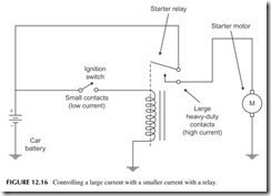
Let’s examine the use of a relay for controlling a larger current with a smaller current. A good example of this is the starting system in your car. A large, heavy-duty DC motor is used to spin the flywheel on the car’s engine to start it. This motor draws a current of hundreds of amperes. To turn the engine and start the car, the battery must be connected to the starter motor. This could be done directly by having the ignition switch connect the battery to the motor. However, this switch would have to have very large contacts to handle the high current. Such a switch would be large and expensive to build. The large heavy wires from the battery to the motor would have to be lengthened and brought up into the car.
A better solution is to use a smaller ignition switch to control the current applied to a relay coil (see Figure 12.16). The relay coil draws considerably less current than the motor; therefore, the switch contacts need not be large
or expensive. The switching contacts on the relay are much larger and will carry the high motor current. When the ignition switch is turned, its contacts close, applying current to the relay coil. The form-A contacts close, connect- ing the battery to the starting motor. When the car starts, the ignition switch is released, the relay drops out, and the starter motor shuts off.
Another application of a relay is remote control. Again, the starting system of a car is a good example. The load to be controlled, in this case the starter motor, is located remotely from the ignition switch. If the ignition switch were used to apply current to the motor, long wires would be required to connect the battery, the motor, and the switch. Heavy wire conductors would have to be used to carry the high current. The longer the interconnecting wires, the higher the resistance of the circuit. While large conductors have minimum resistance, when high current flows through them, voltage drops still occur. The voltage dropped across the interconnecting lines subtract from the battery voltage available for the motor. The voltage drops might be excessive, unless very large, expensive, and inconvenient conductors are used.
To eliminate this problem, a remote relay is used. The relay itself is located near the starter motor and the battery. In this way, the interconnecting leads can be kept short, thereby minimizing voltage drops. Since the relay operates from very low current, longer interconnecting wires can be used to attach it to the ignition switch without noticeable voltage drops.
In some industrial control applications, the load to be operated is located at extreme distances from the switch used to control it. The current controlling the device does not have to be passed through very long conductors if a relay is used. Small conductors running to the switch remotely from the load control the relay while the relay turns the load off and on.
Relay contacts stay closed (or open) as long as power is applied to the coil. This means that the switch operating the relay coil must be kept closed if the relay is to remain actuated. There are applications, however, where it is desir- able to use a momentary contact switch to operate the relay. An example is a pushbutton that, when depressed, causes contacts to be closed and power to be applied to the relay. When the button is released, a spring causes the contacts to open. With such an arrangement, the relay will close momentarily while the button is depressed, but will drop out when the button is released. The objec- tive is to cause the relay to latch into its actuated position when the coil is momentarily pulsed. Such a relay is called a latching relay. Some latching relays use a mechanical arrangement on the armature to cause the contacts to latch closed when the coil is momentarily pulsed.
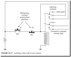
A relay can be made to latch electrically if it has an extra set of contacts. A typical latching circuit is shown in Figure 12.17. This relay has two sets of form-C contacts that operate simultaneously. The lower set of contacts is used to operate the load. The upper set of contacts is used to automatically latch the relay once it is pulsed. Switch S1 is a normally open (NO) momentary contact pushbutton that is used to apply power to the relay coil. Depressing the button
causes the relay coil to operate, closing the contacts. The lower set of contacts operates the load as desired. The upper set of contacts applies the power to the coil. Thus, when pushbutton S1 is released, the circuit to the relay coil remains closed through the upper-latching contacts. To turn off the circuit, normally closed (NC) pushbutton S2 must be depressed. This breaks the relay coil cir- cuit, removing power. The relay drops out, opening the load contacts and the latching contacts.
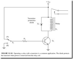
While many relay coils are operated by mechanical switches, others are operated by a transistor. A typical transistor-controlled relay circuit is shown in Figure 12.18. The transistor is operated as a switch. When the base is grounded through contact B on S1, the transistor is cut off and acts as an open switch. Therefore, no current flows in the relay coil. When a voltage is applied to the base resistor, through contact A on S1 , the transistor saturates, acting like a very-low-resistance or “on” switch. Current flows through the relay coil, operating the contacts. Removing the base current from the transistor turns the transistor off, terminating current in the relay. With this arrangement, an even smaller current can be used to control the already small relay current. A base current, of only microamperes, is sufficient to cause the transistor to operate.
In the circuit of Figure 12.18, when base current is removed from the tran- sistor, the transistor will cut off. When current through the relay coil ceases, the magnetic field around it collapses. In doing so, the magnetic field induces a very high voltage in the relay coil. This very high voltage will be applied to the collector of the transistor. This voltage could be as high as several hundred, or
even thousands, of volts, depending on the relay coil. Such a high voltage will damage the transistor. To protect the transistor against such occurrences, some kind of voltage-spike eliminator or surge suppressor must be used across the relay coil. A commonly used protection device is a silicon diode D1, as shown in Figure 12.18. When current is applied to the relay coil through the tran- sistor, the diode is reverse biased and has absolutely no effect on the circuit. When the transistor turns off, the high voltage will be inducted into the coil with the polarity reversed from the supply voltage Vcc. This causes the diode to become forward biased and conduct. Thus, the diode effectively shorts out the high voltage spike, protecting the transistor.
Solenoids
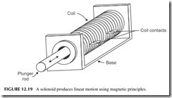
A solenoid is a device that produces linear motion with an electromagnetic coil (see Figure 12.19). A magnetized steel rod called a plunger is inserted into a coil of wire. When a voltage is applied to the coil, a magnetic field is pro- duced. It interacts with the magnetic rod producing attraction and/or repulsion that causes the rod to move into or out of the coil. The rod is usually physi- cally constrained in one or both directions, and is often spring loaded so that it always returns to the same place when power is removed.
Solenoids produce linear motion. They are usually connected to a lever or ratchet mechanism that produces other forms of motion including rotation.
Solenoids are also used in valves to turn off the flow of a liquid or gas. By continuously controlling the current in the coil, the rod may also be precisely set to some position other than off or on. This effect is used in valves to con- tinuously control the opening.
Motors
A motor is a device that converts electrical energy to mechanical energy. The mechanical output is typically the rotation of a shaft. That rotation can then be used directly or converted into other mechanical forms with levers, gears, ratchets, or cams. There are dozens of different motor types but most are cat- egorized as either DC or AC.
Motors: Billions and Billions Sold and Used
Motors are one of those devices we take for granted. We use them every day but don’t realize it. Most motors are hidden but do an enormous amount of physical manipulation. In industry, motors drive machine tools, conveyer belts, pumps, and other mechanical systems. Elevators use big motors.
At home motors are everywhere. Just think a minute and try to identify all the motors you have in your home and in your car. All of your appliances have motors, such as the washer, dryer, dishwasher, and HVAC units. There are motors in your mixers, blenders, and can openers. Shavers and hair dryers have motors. An analog clock is a motor. Then there are the motors in your electronics. In a PC or laptop, there are the fan motor and the ones in your hard disk and CD drives. Your printer, scanner, and copier and fax machine have motors. Your DVD player, CD player, and VCR all have multiple motors.
Then in your car is the starter motor, as well as the motors for windows, seats, mirrors, and windshield wipers.
Can you name some others?
DC Motors
A DC motor operates from a DC voltage source like a battery or power sup- ply. It is made up of a magnet and a rotating coil. When a current is applied to the coil, it forms an electromagnet. The magnetism of the coil interacts with the magnet field, producing rotary motion. The magnet is commonly a perma- nent magnet in smaller DC motors but an electromagnet in larger motors. In the larger motors, a special field coil is energized with DC voltage as well to create the magnetic field.
The main specifications of a motor are its horsepower rating, speed, and torque. Speed and torque are controlled by the amount of current flowing in the coil and/or the strength of the magnetic field. Increasing the voltage applied to the motor usually causes speed and torque to increase. Some kind of electronic control circuit is usually involved to set the speed to the desired value. A vari- able resistor in series with the motor will control its speed, but usually more complex electronic circuits are involved.
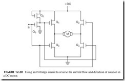
Incidentally, the direction of rotation is determined by the polarity of the DC voltage. Reversing the polarity reverses the magnetic field, thus changing the direction of rotation. Figure 12.20 shows a neat circuit used to change the direction of rotation of a DC motor. This is called an H-bridge and is made up of MOSFET switches. Q2 and Q3 are turned on by a positive input voltage IN. Q5 inverts this voltage to zero, which keeps Q1 and Q4 off. Therefore, current (electrons) flows from ground through Q3 through the motor (M) from left to right through Q2. Setting the input to zero turns off Q2 and Q3 and turns on Q1 and Q4 . Now current flows from ground through Q4 and the motor from right
to left and then through Q1 . This changes the direction of the motor with just a simple off/off input control voltage.
Most DC motors rotate too fast for many applications. A typical speed range is 1000 to 10,000 rpm. To achieve lower speeds, the motor is used in conjunction with a gear box or pulleys.
A special type of DC motor is thestepper motor. This is a DC motor driven by two DC pulse signals. The pulses operate coils or windings that produce a rotating magnetic field. A permanent magnet rotor interacts with the rotat- ing magnetic field to produce motion. The interesting characteristic is that the rotation occurs in increments or steps instead of a continuous rotation as with a standard DC motor. Depending on the number of windings and coils and ele- ments on the rotor, the increments usually vary in increments of 22.5, 18, 15, 7.5, or 3 degrees or smaller. The stepper motor therefore permits very precise positioning. Yet it can be rotated at several thousand rpm if needed.
AC Motors
AC motors usually operate from a 50- or 60-Hz power line. Again the rota- tion is produced by interacting magnetic fields. The speed of rotation is fixed by the number of coils and magnet poles inside the motor. That speed is also often higher than needed, so gears and/or pulleys are used to drop the speed to the desired value.
To change the speed of an AC motor, you must vary the frequency of the AC voltage applied to it. This means that you cannot operate the motor directly from the AC power line if the speed must be changed. Instead, you must use a so-called AC drive. This is a box of electronics that generates a variable frequency AC voltage to apply to the motor. An AC drive takes the AC line input and uses semiconductor switches to produce an AC signal at a different frequency.
Other Actuators
Besides motors, solenoids, and relays, there are a variety of different controlled devices. Valves are common device. Valves are used to turn the flow of a liq- uid or gas on or off. Proportional valves very carefully regulate the amount of flow.
Other devices are hydraulic or pneumatic devices. Hydraulic devices use oil in cylinders to provide mechanical force where needed or position some- thing mechanically. Pneumatic cylinders work with compressed air to apply force or control the position of a device.
THYRISTORS
Many industrial switching circuits are implemented with MOSFETs designed for high voltage and high power. You will sometimes hear these devices called insulated gate field-effect transistors (IGFETs).
Other power-switching devices are also widely used, especially thyristors. A thyristor is a semiconductor device used for switching purposes in industrial control. Like the relay, it is used to apply and control electrical power to motors, heating elements, lights, and other loads in industrial applications. In many applications, thyristors replace relays. A thyristor acts as a switch, but because of its solid-state nature, is far faster in switching than a relay. There are three basic types of thyristors: silicon-controlled rectifiers (SCRs), triacs, and diacs.
Silicon-Controlled Rectifier
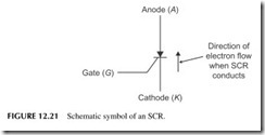
The SCR is a three-terminal thyristor that acts like a silicon rectifier diode whose conductor is controlled by an input current. The schematic symbol for an SCR is shown in Figure 12.21 . The symbol is similar to that of a diode with a cathode and an anode. Note that the third element of the SCR is known as the gate. The SCR will conduct current between cathode and anode, but only if the proper control current is applied to the gate. The gate must be made positive with respect to the cathode in order for the SCR to conduct. When conducting, the SCR acts like a closed switch. The voltage drop across the cathode and anode will be approximately 0.7 to 1.8 volts, depending on the size of the SCR and how much current is flowing through it. When the cathode and anode are reverse biased, current will not flow through the device.
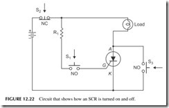
Thyristors, like relays, are generally used to control a larger current with a smaller current. Figure 12.22 shows how an SCR is used as a switch to apply DC power to a light bulb. The load could also be a motor or heating element. The DC voltage is connected so that the cathode and anode of the SCR are forward biased, but no current will flow through the device until a current is applied to the gate. This is done with the switch S1 . With the switch open, no current flows in the gate. Closing the switch, however, applies a positive volt- age to the gate through resistor R1. This causes the SCR to turn on. When it conducts, it acts as a low-resistance “on” switch and the light bulb goes on. At this point, switch S1 may be opened. It is not necessary to maintain current in the gate in order for the device to continue to conduct. The gate current only
needs to be momentary, for it is only required to turn the device on. The device remains on like a latching relay that has been pulsed.
The gate element is only used to turn the SCR on. Removing gate current will not turn the device off. To cause the SCR to stop conducting, the circuit must be broken. This can be done with a momentary-contact, normally closed pushbutton, in series with the circuit, like S2 in Figure 12.22. Depressing this pushbutton will break the circuit, stopping the current in the SCR, and the light bulb will go off. To turn the bulb back on, S1 must again be depressed to apply gate current momentarily.
Another way to stop conduction is to momentarily short around the SCR, as shown in Figure 12.15. When switch S3 is closed momentarily, current will flow through it and the bulb, bypassing the SCR. The current in the SCR will drop to zero. When switch S3 is opened, the circuit will be off.
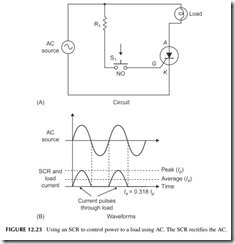
While SCRs are sometimes used to control DC power, in most applications they are used to control AC. Figure 12.23A shows the SCR used to apply AC to a light bulb. If switch S1 is closed, gate current will be applied to the device. The device, however, will only conduct when the anode is made positive with respect to the cathode. This, of course, occurs when the applied AC voltage has the correct polarity. Since the SCR operates as a rectifier diode, current will only flow through the device on the positive half-cycles of the sine wave. The current through the light bulb will be a pulsating DC, as illustrated in Figure 12.23B. The brightness of the lamp will depend on the average amount of current flowing.
The average amount of current through the light bulb, or other load, can be controlled by using the gate element. Various electronic circuits are used to adjust the time when the SCR turns on. By turning on the SCR at the appro- priate time in the positive half-cycle, the duration of the current flow can be controlled. The longer the current is allowed to flow, the higher the average
current in the load. By changing the control point, the brightness of the bulb can be varied.
Diac
A diac is a two-terminal semiconductor device that conducts in either direc- tion when a voltage of a specific level is exceeded. This voltage is called the triggering voltage. Typical diac triggering voltages are in the 20- to 45-volt range. The diac is used as a triggering device for SCR and triacs as it deter- mines when the device will conduct or cut off.
Triac
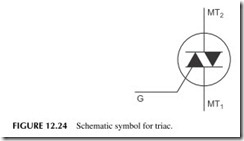
A triac is another three-terminal thyristor. Its operation is similar to that of an SCR, but the triac will conduct in either direction. The schematic symbol for the triac is shown in Figure 12.24. Current will flow from main terminal 1 (MT1)
to main terminal 2 (MT2), or from main terminal 2 (MT2) to main terminal 1 (MT1), depending on the polarity of the voltage applied, and if the gate trig- gers the device on.
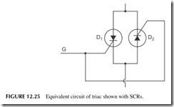
An approximate, equivalent circuit of the triac is shown in Figure 12.25. Here, two SCRs are connected back to back with their gates connected together. Current can flow in either direction, depending on whether D1 or D2 conducts. Of course, SCR conduction depends on whether a gate-triggering current is applied. Triacs, like SCRs, are used primarily to switch AC volt- age to a load. If gate current is applied continuously, the triac will conduct in both forward and backward directions, causing both positive and negative half- cycles of the AC to be applied to a load.
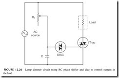
Figure 12.26 shows a circuit used for light-dimming purposes. The load is a light bulb. An RC phase shifter and diac-triggering device are used on the gate of the triac. Assume that the diac has a triggering voltage of 30 volts. If the voltage across the diac is less than 30 volts, it will not conduct. As soon as the 30-volt point is reached or exceeded, the diac rapidly conducts and fires the SCR. Keep in mind that the diac is a bidirectional device, and that current will flow through it in either direction if the bias voltage in either direction exceeds the triggering voltage level.
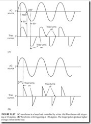
The triac will conduct on both positive and negative half-cycles of the applied AC. The phase shifter made up of R1 and C will set the triggering delay. It will determine at what point in the AC cycle the diac will fire and apply gate current to the triac. Figure 12.27 shows the waveforms at two dif- ferent phase-shift points in the circuit. Note that current flows through the load in both the positive and negative half-cycles, but the duration of current flow depends on the point where the gate triggers. In Figure 12.27, the average cur- rent through the load will be relatively high at a 60-degree phase shift, and the bulb will be bright. At 120 degrees, the triggering point is late in each half- cycle, allowing only a small amount of current to flow through the bulb. The bulb, therefore, will glow dimly. Adjusting R1 will allow the brightness of the bulb to be varied from nearly full on to full off. This is the circuit normally used in household and industrial light dimmers.
This same circuit can be used to control the speed of AC motors. In con- necting a hand drill as the load, for example, R1 will vary the speed of rotation.
Triacs are also widely used as solid-state relays.
PROGRAMMABLE LOGIC CONTROLLERS
A very popular type of controller used in industry and process control is a spe- cialized computer called a programmable logic controller (PLC), or program- mable controller. It uses sensors to monitor physical variables and generates output control signals to operate heating elements, motors, pumps, solenoids, and other devices. The PLC, however, contains a microprocessor that can be
programmed in a special language that permits the PLC to be customized to the particular control function. In this way, a standard PLC can be programmed and configured for virtually any application. The PLC is by far one of the most popular and versatile control devices in use in industry.
The main function of a PLC is factory automation. It is a versatile special- purpose computer that can be quickly and easily reconfigured to meet changes
and additions in factories, plants, and other operations that routinely need to con- trol and sequence various machines and processes. While an embedded controller or personal computer could be used in some operations, they are harder to pro- gram and apply and are less flexible when rapid changes are needed. Furthermore, these common microcomputers are not designed for the factory environment. But PLCs are rugged and hardened against the harsh environment of most factories and plants. They can withstand the temperature ranges, vibration, and dirty con- ditions usually existing in a manufacturing or process control setting.
Organization
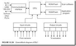
A general block diagram of a PLC is shown in Figure 12.28. It is like most other microcomputer diagrams but there are some differences. A microproces- sor is at the heart of the design. This CPU is coupled to a ROM where a special control program is stored. This program implements the basic scan operational mode of the PLC. RAM is also available to store the application program. Flash memory may also be used in place of RAM.
The key to the PLC’s versatility is its extensive I/O section. It has a variety of input and output modules. These are fixed in small, single-function PLCs, but in the larger more flexible units, the PLC is designed to accept a wide variety of separate I/O modules. These usually plug into a rack containing the main PLC unit and power supply. The different I/O modules let the user cus- tomize the PLC to the specific application.
Some examples of I/O modules are digital inputs and outputs with common logic levels or conditioned levels, analog-input modules that accept analog signals from sensors, and analog output modules that generate analog out- puts for controlling actuators of almost any kind. A huge variety is available.
A communications interface is also available so that the PLC can talk to exter- nal devices like a PC or other PLCs that are connected to form a larger control system. RS-232 and RS-485 serial interfaces are common as is USB. The pro- gram describing the operations to be implemented is developed on an external PC, and then downloaded to the PLC RAM or flash memory via the USB or RS-232 interfaces.
Operation
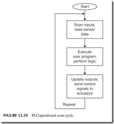
The general operation of a PLC is shown in Figure 12.29. When the PLC is started, the internal operational program looks at the application program and interprets what is to be done. The sequence of operations is to first scan the inputs. The PLC looks at what the various sensors are doing. It gets a status update from the application itself. The program then interprets what to do next based on the application program. It processes the input to determine what the outputs should be. Then it updates the outputs to carry out the application. Then the cycle repeats itself at a high rate of speed. The inputs are scanned and outputs updated every 1 millisecond or so, slower or faster as the applica- tion requires.
A simple example is using a switch to turn on a motor. The switch con- tacts are connected to an input module by wires. Output wires connect to a relay that in turn is used to operate the motor. As the PLC is scanning, it sees that the switch is off, so it does nothing. But as soon as the switch is turned
on, the next scan detects this new condition. The program then tells the CPU that if the switch is on, turn on the relay. An output signal is sent to the output module, which then actuates an external relay. The relay contacts then turn the motor on. If the switch is then turned off, the next scan detects this condition and causes the output to turn off the relay and motor.
Programming
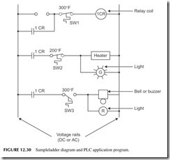
As for programming, PLCs can be programmed in various ways. Most PLC vendors have special languages to do the programming. In some cases, stan- dard BASIC or C languages may be used. One widely used approach is a graphical language called ladder logic. Ladder logic is the technology that the PLC replaced decades ago. Control systems were made with relays, and they were wired so the diagram looked like a ladder (see Figure 12.30). The two vertical lines represent a DC or AC voltage source. Circuits are then connected between these two “rails,” forming rungs on the ladder. The circuits are con- nections of switches, relays, and other components. The software allows the user to build the ladder logic program on the screen, while a translation pro- gram in the PC converts it into the binary code that the PLC can execute.
This particular circuit in Figure 12.30 does the following: when the ON pushbutton is pressed, current is applied to relay coil 1CR through normally closed contacts of SW1. SW1 is a thermal switch whose contacts stay closed as long as the temperature is less than 300 degrees Fahrenheit (300°F). If the temperature rises above that level, the contacts open, thereby breaking the cir- cuits. Relay contacts 1CR around the ON pushbutton latch the circuit on when the ON pushbutton is released.
In the next “rung” of the ladder contacts 1CR are on the relay. They close when the relay turns on. This applies voltage to a heating element. This current flows through the normally closed contacts of thermal switch SW2. A green light in parallel with the heating elements turns on to indicate the heater is on.
When the heater temperature reaches 200°F, SW2 opens, turning off the heater and the green light. As the heater cools, SW2 will then close again, applying voltage to the heater. The heater will then cycle off and on keeping its temperature near the 200°F value.
If the temperature should rise above 300°F due to a failure of SW2 °F then SW1 opens. Relay 1CR is turned off, and its contacts open, releasing the latch on rung 1 and opening the circuit on rung 2. Thermal switch SW3 closes at 300°F, turning on a red light and ringing an alarm bell.
This example could be programmed with a graphical ladder logic program or with special commands and syntax of a traditional programming language.
In addition to being able do simple off/off tasks common to industrial control, special hardware in the PLC can also implement counters and timers so that external events can be counted and the sequencing of events can be programmed.
Project 12.1
Build a Robot
Robots are great examples of basic industrial control. While most industrial robots are usually manipulator arms, you can actually buy a mobile robot with wheels that can be programmed for motion and other functions. A wide range of kits are available. It is a great way to get familiar with sensors, a microcomputer control- ler, and various actuators. Typical inputs are switches, photo cells, temperature sensors, and common outputs are relays, lights, and motors.
Some recommended kits are those made by Lego and Parallax. Suggested web- sites to learn more follow:
Lego Mindstorms NXT: www.mindstorms.lego.com Parallax: www.parallax.com
Two magazines regularly cover robots from a hobbyist/experimenter view- point. These are Nuts & Volts and Servo. You may be able to find these at a news- stand; otherwise, go to their websites:
Nuts & Volts Magazine: www.nutsvolts.com
Servo Magazine: www.servomagazine.com
