The rather involved d–q (space phasor) model with skin effect and saturation may be used directly to investigate the induction machine transients. More practical (simpler) solutions have also been proposed. They are called reduced order models. [9,10,11]
The complete model has, for a single cage, a fifth order in d–q writing and a third order in complex variable writing ( Ψs , Ψr , ωr).
![]()
![]() In general, the speed transients are considered slow, especially with inertia or high loads, while stator flux Ψs and rotor flux Ψr transients are much faster for voltage-source supply.
In general, the speed transients are considered slow, especially with inertia or high loads, while stator flux Ψs and rotor flux Ψr transients are much faster for voltage-source supply.
![]() The intuitive way to obtain reduced models is to ignore fast transients, of the stator, dΨs = 0 (in synchronous coordinates) or stator and rotor transients dt
The intuitive way to obtain reduced models is to ignore fast transients, of the stator, dΨs = 0 (in synchronous coordinates) or stator and rotor transients dt
ddtΨs = ddtΨr = 0 (in synchronous coordinates) and up date the speed by
solving the motion equation by numerical methods.
![]()
![]() This way, third order ddtΨs = 0 or first order ddtΨs = ddtΨr = 0 models
This way, third order ddtΨs = 0 or first order ddtΨs = ddtΨr = 0 models
are obtained. The problem is that the results of such order obscure reductions inevitably fast transients. Electric (supply frequency) torque transients (due to rotor flux transients) during starting, may still be visible in such models, but for too long a time interval during starting in comparison with the reality.
So there are two questions about model order reduction.
• What kind of transients are to be used
• What torque transients have to be preserved
In addition to this, small and large power IMs seem to require different reduced orders to produce practical results in simulating a group of IMs when the computation time is critical.
Neglecting stator transients
In this case, in synchronous coordinates, the stator flux derivative is considered zero (Equations (13.55)).
0+(1+ ω τj 1 s ‘)Ψ = τs s ‘Vs + Kr Ψr
τr ‘ddtΨr +(1+ j(ω −ω1 r ))Ψ = τr r ‘Vr + Ks Ψs
T = − 32 p Re j1 ( Ψr ri * ) ; ir* = σ−1 ΨLrr −Ψs L LLs m r (13.70) e
pJ1 ddtωr = Te −Tload
With two algebraic equations, there are three differential ones (in real d–q variables).
For cage rotor IMs ,
Ψ =s τs ‘V1+ ω τs j+ K1 rsΨ‘ r (13.71)
ddtΨr = − (1+ j(ω −ω1 r ))+1+ ω τK Kjs 1r s ‘ Ψτrr’ + (1τ ⋅+ ω τs ‘ Vj s1 ⋅sK‘)τs r ‘ (13.72)
Te = 3 p
2 1 Imσ Ψ Ψ−1 r s* L LLs m r = 32 p1 σL L−s1Lrm ImΨr τs ‘V1− ω τs* j+ K1 rsΨ‘ r* (13.73)
ddtωr = pJ1 (Te −Tload )
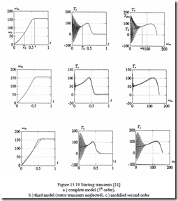
Fast (at stator frequency) transient torque pulsations are absent in this thirdorder model (Figure 13.8b).
The complete model and third-order model for a motor with Ls = 0.05H, Lr = 0.05H, Lm = 0.0474H, Rs = 0.29Ω, Rr = 0.38Ω, ω1 = 100πrad/s, Vs =
![]() 220 2 V, p1 = 2, J = 0.5 Kgm2 yields, for no-load, starting
220 2 V, p1 = 2, J = 0.5 Kgm2 yields, for no-load, starting
![]() 220 2 V, p1 = 2, J = 0.5 Kgm2 yields, for no-load, starting transient results as shown in Figure 13.19. [11]
220 2 V, p1 = 2, J = 0.5 Kgm2 yields, for no-load, starting transient results as shown in Figure 13.19. [11]
It is to be noted that steady-state torque at high slips (Figure 13.19a) falls into the middle of torque pulsations, which explains why calculating no-load starting time with steady-state torque produces good results.
A second-order system may be obtained by considering only the amplitude transients of Ψr in (13.73) [11], but the results are not good enough in the sense that the torque fast (grid frequency) transients are present during start up at higher speed than for the full model.
Modified second-order models have been proposed to improve the precision of torque results [11] (Figure 13.19c), but the results are highly dependent on motor parameters and load during starting. So, in fact, for starting transients when the torque pulsations (peaks) are required with precision, model reduction may be exercised with extreme care.
The presence of leakage saturation makes the above results more of academic interest.
Considering leakage saturation
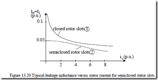
As shown in Chapter 9, the leakage inductance (Lsc = Lsl + Lrl = Ll) decreases with current. This reduction is accentuated when the rotor has closed slots and more moderate when both, stator and rotor, have semiclosed slots (Figure 13.20).
The calculated (or measured) curves of Figure 13.20 may be fitted with analytical expressions of RMS rotor current such as [12]
Xl = ω1Ll = K1 + K2 Ir −K for curve 1 (13.74)
Xl =ω1Ll = K3 − K4 tanh(K I3 3r − K6 )+ K7 cos(K I 8 r ) for curve 2 (13.75) During starting on no-load the stator current envelope Isp(t) varies approximately as [12]
Isp ≈ Q I1 rK (13.76)
+ tK0
![clip_image002[6] clip_image002[6]](http://machineryequipmentonline.com/electric-equipment/wp-content/uploads/2017/04/clip_image0026_thumb2.gif) 3 1 t + tK0t 2
3 1 t + tK0t 2
Q1 reflects the effect of point on wave connection when nonsymmetrical switching of supply is considered to reduce torque transients (peaks) [13]
![]() Q1 ≈ 2+ RX Ssl (+ RK )r ⋅(cos2 α +sin2 (α +β)) (13.77)
Q1 ≈ 2+ RX Ssl (+ RK )r ⋅(cos2 α +sin2 (α +β)) (13.77)
α–point on wave connection of first phase to phase (b-c) voltage. β−delay angle in connecting the third phase.
(It has been shown that minimum current (and torque) transients are obtained for α = π/2 and β = π/2. [14])
As the steady-state torque gives about the same starting time as the transient one, we may use it in the motion equation (for no-load).
![]() pJ1 dωr = 3Vωph1p21Rr ⋅ Rs + RSr 12S+ω1L Sl2 = Te (13.78)
pJ1 dωr = 3Vωph1p21Rr ⋅ Rs + RSr 12S+ω1L Sl2 = Te (13.78)
dt
![]() We may analytically integrate this equation with respect to the time up to the breakdown point: SK slip, noting that d
We may analytically integrate this equation with respect to the time up to the breakdown point: SK slip, noting that d![]() .
.
![]() tK0 = 3VJω21R2 2 ⋅12 (Rs2 + ω( 1L Sl( K0 ))2 )(1−S2K0 )+
tK0 = 3VJω21R2 2 ⋅12 (Rs2 + ω( 1L Sl( K0 ))2 )(1−S2K0 )+
ph r
(13.79)
+ 2R R 1 Ss r ( − K0 )+ Rr2 lnS1K0
![]() with SK0 = 2 + ω(R1rL Sl ( K0 ))2 (13.80)
with SK0 = 2 + ω(R1rL Sl ( K0 ))2 (13.80)
Rs
On the other hand, the base current IrK is calculated at standstill.
![]() = Vph (13.81) IrK ( 2 + ω( L 1l ( ))2
= Vph (13.81) IrK ( 2 + ω( L 1l ( ))2
Rs + Rr )
Introducing Ll as function of Ir from (13.74) or (13.75) into (13.81) we may solve it numerically to find IrK.
Now we may calculate the time variation of Isp (the current envelope) versus time during no-load starting. The current envelope compares favourably with complete model results and with test results. [12]
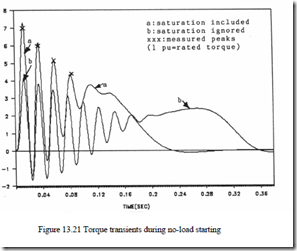
As the current envelope varies with time, so does the leakage inductance Ll(Isp) and, finally, the torque value in (13.78) is calculated as a function of time through its peak values, since from Equation (13.78) we may calculate slip (S) versus time.
Sample results in Figure 13.21 [12] show that the approximation above is really practical and that neglecting the leakage saturation leads to an underestimation of torque peaks by more than 40%!
Large machines: torsional torque
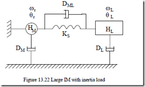
Starting of large induction machines causes not only heavy starting currents but also high torsional torque due to the large masses of the motor and load which may exhibit a natural torsional frequency in the range of electric torque oscillatory components.
Sudden voltage switching (through a transformer or star/delta), low leakage time constants τs’ and τr’, and a long starting interval cause further problems in starting large inertia loads in large IMs. The layout of such a system is shown in Figure 13.22.
The mechanical equations of the rotating masses in Figure 13.22, with
elastic couplings, is straightforward. [15]
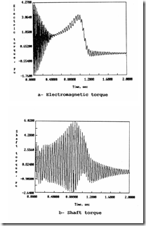
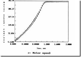
Equations (13.82) and (13.83) may be solved by numerical methods such as Runge–Kutta−Gill. For the data [15] rs = 0.0453 p.u., xs = 2.1195 p.u., rr = 0.0272 p.u., xr = 2.0742 p.u., xm = 2.042 p.u., HM = 0.3 seconds, HL = 0.74 seconds, DL = DM = 0, DML = 0.002 p.u./(rad/s), KS = 30 p.u./rad, TL = 0.0, ω0 = 377 rad/s, the electromagnetic torque (te), the shaft torque (tsh), and the speed ωr are shown in Figure 13.23. [15]
The current transients include a stator frequency current component in the rotor, a slip frequency current in the rotor, and d.c. decaying components both in the stator and rotor. As expected, their interaction produces four torque components: unidirectional torque (by the rotating field components), at supply frequency ω0, slip frequency S ω0, and at speed frequency ωm.
The three a.c. components may interact with the mechanical part whose natural frequency fm is [15]
Figure 13.23 Starting transients of a large motor with elastic coupling of inertial load
The torsional torque in Figure 13.23b (much higher than the electromagnetic torque) may be attributed to the interaction of the slip frequency component of electromagnetic torque, which starts at 60 Hz (S = 1) and reaches 26 Hz as the speed increases (S⋅60 Hz = 26Hz, ωm = (1 – S)⋅ω0 = 215rad/s). The speed frequency component (ωm) of electromagnetic torque is active when ωm = 162 rad/s (ωm = 2πfm), but it turns out to be small.
A good start would imply the avoidance of torsional torques to prevent shaft damage.
For example, in the star/delta connection starting, the switching from star to delta may be delayed until the speed reaches 80% of rated speed to avoid the torsional torques occurring at 215 rad/s and reducing the current and torque peaks below it.
The total starting time with star/delta is larger than for direct (full voltage) starting, but shaft damage is prevented.
Using an autotransformer with 40%, 60%, 75%, 100% voltage steps further reduces the shaft torque but at the price of even larger starting time.
Also, care must be exercised to avoid switching voltage steps near ωm = 215 rad/s (in our case).
