Arithmetic
We have seen how the process of counting in binary is carried out. Operations using the number base of 2 are characterized by a number of useful tricks that are often used. Simple
counting demonstrates the process of addition and, at first sight, the process of subtraction would need to be simply the inverse operation. However, since we need negative numbers in order to describe the amplitude of the negative polarity of a waveform, it seems sensible to use a coding scheme in which the negative number can be used directly to perform subtraction. The appropriate coding scheme is the two’s complement coding scheme.
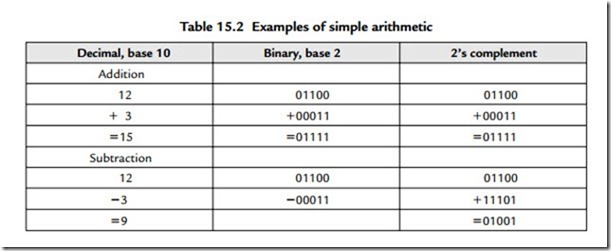
We can convert from a simple binary count to a two’s complement value very simply. For positive numbers simply ensure that the MSB is a zero. To make a positive number into a negative one, first invert each bit and then add one to the LSB position thus:
We must recognize that since we have fixed the number of bits that we can use in each word (in this example to 5 bits) then we are naturally limited to the range of numbers we can represent (in this case from +15 through 0 to -16). Although the process of forming two’s complement numbers seems lengthy, it is performed very speedily in hardware. Forming a positive number from a negative one uses the identical process. If the binary numbers represent an analogue waveform, then changing the sign of the numbers is identical to inverting the polarity of the signal in the analogue domain. Examples of simple arithmetic should make this a bit more clear:
Since we have only a 5-bit word length any overflow into the column after the MSB needs to be handled. The rule is that if there is overflow when a positive and a negative number are added then it can be disregarded. When overflow results during the addition of two positive numbers or two negative numbers then the resulting answer will be incorrect if the overflowing bit is neglected. This requires special handling in signal processing, one approach being to set the result of an overflowing sum to the appropriate largest positive or negative number. The process of adding two sequences of numbers that represent two audio waveforms is identical to that of mixing the two waveforms in the analogue domain. Thus when the addition process results in overflow the effect is identical to the resulting mixed analogue waveform being clipped.
We see here the effect of word length on the resolution of the signal and, in general, when a binary word containing n bits is added to a larger binary word comprising m bits the resulting word length will require m + 1 bits in order to be represented without the effects of overflow. We can recognize the equivalent of this in the analogue domain where we know that the addition of a signal with a peak-peak amplitude of 3V to one of 7V must result in a signal whose peak-peak value is 10V. Don’t be confused about the rms value of the resulting signal, which will be assuming uncorrelated sinusoidal signals.
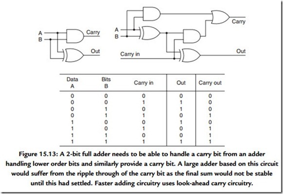
A binary adding circuit is readily constructed from the simple gates referred to earlier, and Figure 15.13 shows a 2-bit full adder. More logic is needed to be able to accommodate wider binary words and to handle the overflow (and underflow) exceptions.
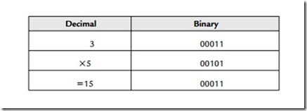
If addition is the equivalent of analogue mixing, then multiplication will be the equivalent of amplitude or gain change. Binary multiplication is simplified by only having 1 and 0 available since 1 X 1 = 1 and 1 X 0 = 0.
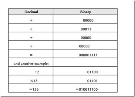
Since each bit position represents a power of 2, then shifting the pattern of bits one place to the left (and filling in the vacant space with a 0) is identical to multiplication by 2. The opposite is, of course, true of division. The process can be appreciated by an example:
The process of shifting and adding could be programmed in a series of program steps and executed by a microprocessor but this would take too long. Fast multipliers work by arranging that all of the available shifted combinations of one of the input numbers are made available to a large array of adders, while the other input number is used to determine which of the shifted combinations will be added to make the final sum.
The resulting word width of a multiplication equals the sum of both input word widths. Further, we will need to recognize where the binary point is intended to be and arrange to shift the output word appropriately. Quite naturally the surrounding logic circuitry will have been designed to accommodate a restricted word width. Repeated multiplication must force the output word width to be limited. However, limiting the word width has a direct impact on the accuracy of the final result of the arithmetic operation. This curtailment of accuracy is cumulative since subsequent arithmetic operations can have no knowledge that the numbers being processed have been “damaged.”
Two techniques are important in minimizing the “damage.” The first requires us to maintain the intermediate stages of any arithmetic operation at as high an accuracy as possible for as long as possible. Thus although most conversion from analogue audio to digital (and the converse digital signal conversion to an analogue audio signal) takes place using 16 bits, the intervening arithmetic operations will usually involve a minimum of 24 bits.
The second technique is called dither, which will be covered fully later. Consider, for the present, that the output word width is simply cut (in the example given earlier such as to produce a 5-bit answer). The need to handle the large numbers that result from multiplication without overflow means that when small values are multiplied they are likely to lie outside the range of values that can be expressed by the chosen word width. In the example given earlier, if we wish to accommodate the most significant digits of the second multiplication (156) as possible in a 5-bit word, then we shall need to lose the information contained in the lower four binary places. This can be accomplished by shifting the word four places (thus effectively dividing the result by 16) to the right and losing the less significant bits. In this example the result becomes 01001, which is equivalent to decimal 9. This is clearly only approximately equal to 156/16.
When this crude process is carried out on a sequence of numbers representing an audio analogue signal, the error results in an unacceptable increase in the signal-to-noise ratio. This loss of accuracy becomes extreme when we apply the same adjustment to the lesser product of 3 X 5 = 15 since, after shifting four binary places, the result is zero. Truncation is thus a rather poor way of handling the restricted output word width. A slightly better approach is to round up the output by adding a fraction to each output number just prior to truncation. If we added 00000110, then shifted four places and truncated the output would become 01010 (=1010), which, although not absolutely accurate, is actually closer to the true answer of 9.75. This approach moves the statistical value of the error from 0 to -1 toward +/- 0.5 of the value of the LSB, but the error signal that this represents is still very highly correlated to the required signal. This close relationship between noise and signal produces an audibly distinct noise that is unpleasant to listen to.
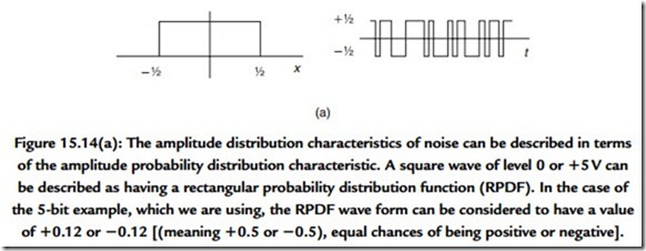
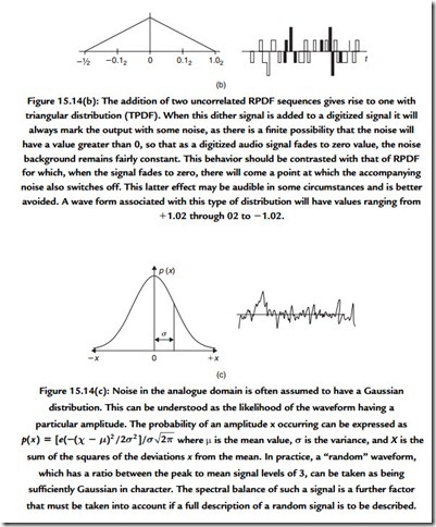
An advantage is gained when the fraction that is added prior to truncation is not fixed but random. The audibility of the result is dependent on the way in which the random number is derived. At first sight it does seem daft to add a random signal (which is obviously a form of noise) to a signal that we wish to retain as clean as possible. Thus the probability and spectral density characteristics of the added noise are important. A recommended approach commonly used is to add a random signal that has a triangular probability density function (TPDF) (Figure 15.14). Where there is sufficient reserve of processing power it is possible to filter the noise before adding it in. This spectral shaping is used to modify the spectrum of the resulting noise (which you must recall is an error signal) such that it is biased to those parts of the audio spectrum where it is least audible. The mathematics of this process are beyond this text.
A special problem exists where gain controls are emulated by multiplication. A digital audio mixing desk will usually have its signal levels controlled by digitizing the position of a physical analogue fader (certainly not the only way by which to do this, incidentally). Movement of the fader results in a stepwise change of the multiplier value used.
When such a fader is moved, any music signal being processed at the time is subjected to stepwise changes in level. Although small, the steps will result in audible interference unless the changes that they represent are themselves subjected to the addition of dither. Thus although the addition of a dither signal reduces the correlation of the error signal to the program signal, it must, naturally, add to the noise of the signal. This reinforces the
need to ensure that the digitized audio signal remains within the processing circuitry with as high a precision as possible for as long as possible. Each time that the audio signal has its precision reduced it inevitably must become noisier.
