The Acoustic Environment Indoors
The moment we enclose the sound source, we greatly complicate the transmission of its output. We have considered one extreme when we put the sound source in a well-elevated position and observed the sound being totally absorbed by the “space” around it. Now, let us go to the opposite extreme and imagine an enclosed space that is completely reflective. The sound source would put out sound energy, and none of it would be absorbed. If we continued to put energy into the enclosure long enough, we could theoretically arrive at a pressure that would be explosive. Human speech power is quite small. It has been stated by Harvey Fletcher in his book Speech and Hearing in Communication that it would take “…500 people talking continuously for one year to produce enough energy to heat a cup of tea.” Measured at 39.37 in (3.28 ft), a typical male talker generates 67.2 dB-SPL, or 34 μW of power, and a typical female talker generates 64.2 dB-SPL, or 18 μW. From a shout at this distance (3.28 ft) to a whisper, the dB LP ranges from 86 to 26 dB, or a dynamic range of about 60 dB. Not only does the produced sound energy tend to remain in the enclosure (dying out slowly), but it tends to travel about in the process.
Let us now examine the essential parameters of a typical room to see what does happen. First, an enclosed space has an internal volume (V), usually measured in cubic feet. Second, it has a total boundary surface area (S), measured in square feet (floor, ceiling, two side walls, and two end walls). Next, each of the many individual surface areas has an absorption coefficient. The average absorption coefficient (a) for all the surfaces together is found by
where s1,2,…n are the individual boundary surface areas in square feet, a– are the individual absorption coefficients of the individual boundary surface areas, and S is the total boundary surface area in square feet.
The reflected energy is 1 – a.
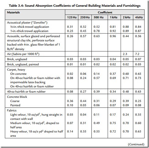
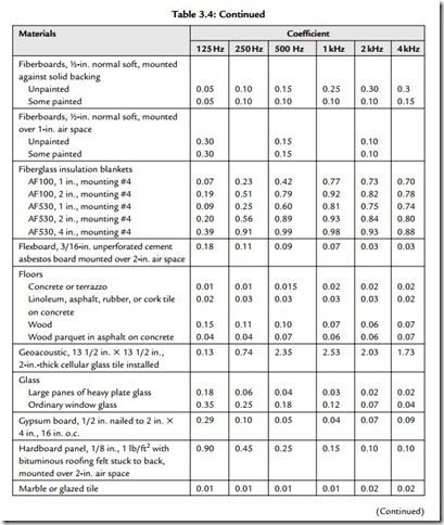
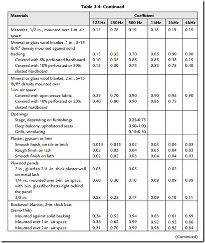
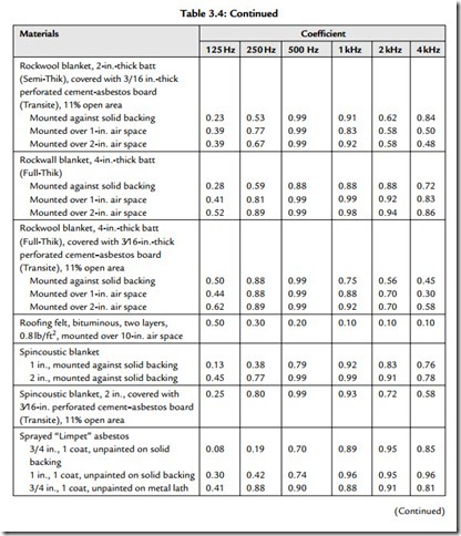
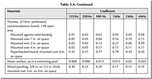
Table 3.4 gives typical absorption coefficients for common materials. These coefficients are used to calculate the absorption of boundary surfaces (walls, floors, ceilings, etc.).
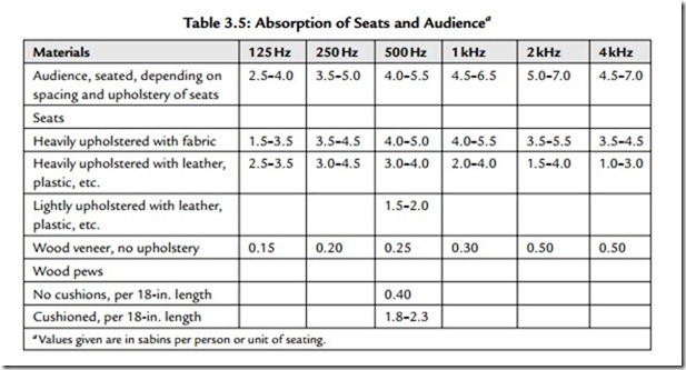
Table 3.5 gives typical absorption units in sabins rather than percentage figures. Sabins are either in per-unit figures or in units per length.
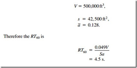
Finally, the room will possess a reverberation time, RT60. This is the time in seconds that it will take a steady-state sound, once its input power is terminated, to attenuate 60 dB. For the sake of illustration, assume a room with the following characteristics:
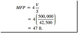
If a sound is generated in the sample space, part of it will travel directly to a listener and undergo inverse-square-law level change on its way. Some more of it will arrive after having traveled first to some reflecting surface, and still more will finally arrive having undergone several successive reflections (each 47 ft apart on the average). Each of these signals will have had more attenuation at some frequencies than at others because of divergence, absorption, reflection, refraction, diffraction, etc.
We can look at this situation in a different manner. Each sound made will have traveled 4.5 s X 1130 ft/s, or 5085 ft. Since the mean free path is 47 ft, then we can assume each
sound underwent approximately 108 reflections in this sample space before becoming inaudible. The result is a lot different than hearing the sound just once.
Build-Up of the Reverberant Sound Field
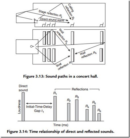
Figure 3.13 shows the paths of direct sound and several reflected sound waves in a concert hall. Reflections also occur from balcony faces, rear wall, niches, and any other reflecting surfaces. We can obtain a chart such as that shown in Figure 3.14 if we plot the amplitude of a short-duration signal vertically and the time interval horizontally. This diagram shows that at listener’s ears, the sound that travels directly from the performer arrives first, and after a gap, reflections from the walls, ceiling, stage enclosure, and other reflecting surfaces arrive in rapid succession. The height of a bar suggests the loudness of the sound. This kind of diagram is called a reflection pattern. The initial-signal-delay gap can be measured from it.
Figure 3.14 illustrates the decay of the reverberant field. Here the direct sound enters at the left of the diagram. The initial-signal-delay gap is followed by a succession of sound reflections. The reverberation time of the room is defined as the length of time required for the reverberant sound to decay 60 dB.
We will encounter the effects of delay versus attenuation again when we approach the calculation of articulation losses of consonants in speech.
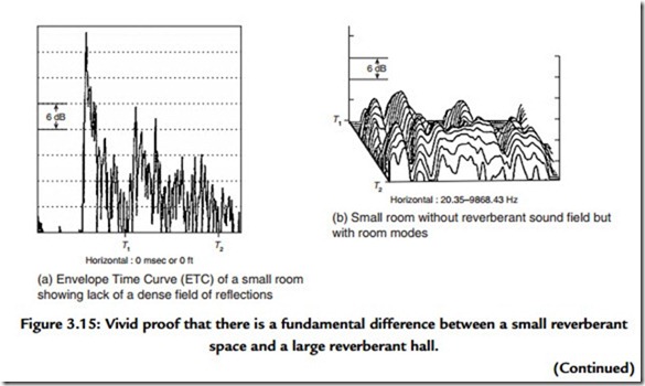
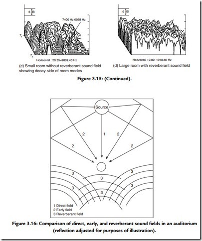
Figure 3.15 shows measurements from an analyzer made in both large and small rooms. Figure 3.16 shows that the sound arriving at the listener has at least three distinct divisions:
1. The direct sound level LD.
2. The early reflections level LRE.
3. The reverberant sound level LR.
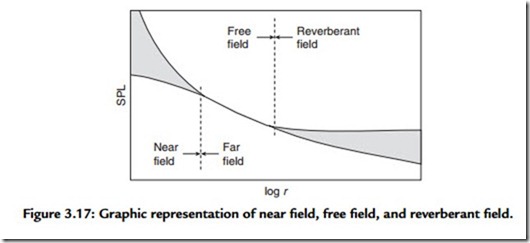
source continues to put energy into the room at a reasonably regular rate. This gives rise to a number of basic sound fields (Figure 3.17):
1. The near field.
2. The far free field.
3. The far reverberant field.
The near field does not behave predictably in terms of LP versus distance because the particle velocity is not necessarily in the direction of travel of the wave, and an appreciable tangential velocity component may exist at any point. This is why measurements are usually not made closer than twice the largest dimension of the sound source. In the far free field, the inverse-square-law level change prevails. In the far reverberant field, or diffuse field, the sound-energy density is very nearly
uniform. Measuring low-frequency loudspeakers is an exception to the rule, and such measurements are often made in the pressure response zone of the device.
Conclusion
The study of acoustics for sound system engineers divides into outdoors and indoors with indoor acoustics again divided into large room acoustics and small room acoustics. Classical Sabinian acoustics are rapidly being refined where applicable, discarded where misapplied, and reexamined where the “fine structure of reverberation” is the meaningful parameter. The digital computer has fueled basic research into the mathematics of enclosed spaces, and modern analyzers have served to verify or deny the validity of the theories put forward.

