filter circuits
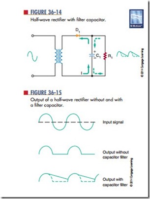
The output of the rectifier circuit is a pulsating DC voltage. This is not suitable for most electronic circuits, so a filter follows the rectifier in most power supplies. The filter converts the pulsating DC volt- age to a smooth DC voltage. The simplest filter is a capacitor filter connected across the output of the rectifier (Figure 36-14). Figure 36-15 compares the outputs of a rectifier without and with the addition of a filter capacitor.
A capacitor affects the circuit in the following manner. When the anode of the diode is positive, current flows in the circuit. At the same time, the filter capacitor charges to the polarity indicated in Figure 36-14. After 90° of the input signal, the capacitor is fully charged to the peak potential of the circuit.
When the input signal starts to drop in the negative direction, the capacitor discharges through the load.
The resistance of the load controls the rate the capacitor discharges by the RC time constant. The discharge time constant is long compared to the cycle time. Therefore the cycle is completed before the capacitor can discharge. Thus, after the first quarter cycle, the current through the load is supplied by the discharging capacitor. As the capacitor discharges, the voltage stored in the capacitor decreases. However, before the capacitor can completely discharge, the next cycle of the sine wave occurs. This causes the anode of the diode to become positive, allowing the diode to
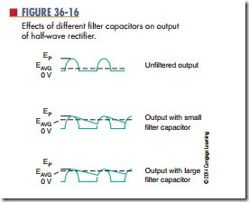
conduct. The capacitor recharges and the cycle repeats. The end result is that the pulses are smoothed out and the output voltage is actually raised (Figure 36-16).
A larger capacitor has a longer RC time constant, resulting in a slower discharge of the capacitor and thus raising the output voltage. The presence of the capacitor allows the diode in the circuit to conduct for a shorter period of time. When the diode is not con- ducting, the capacitor is supplying the current to the load. If the current required by the load is large, a very large capacitor must be used.
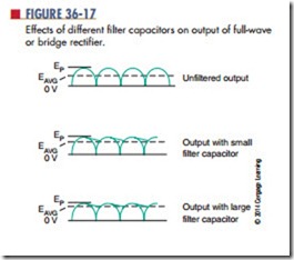
A capacitor filter across a full-wave or bridge rectifier behaves much like the capacitor filter in the half-wave rectifier just described. Figure 36-17 shows the output of a full-wave or bridge rectifier. The ripple frequency is twice that of the half-wave rectifier. When
the capacitor filter is added to the output of the rectifier, the capacitor does not discharge very far before the next pulse occurs. The output voltage is high. If a large capacitor is used, the output equals the peak voltage of the input signal. Thus, the capacitor does a better job of filtering in a full-wave circuit than in a half-wave circuit.
The purpose of the filter capacitor is to smooth out the pulsating DC voltage from the rectifier. The ripple remaining on the DC voltage determines the filter’s performance. The ripple can be made lower by using a large capacitor or by increasing the load resistance. Typically, the load resistance is determined by the circuit design. Therefore, the size of the filter capacitor is determined by the amount of the ripple.
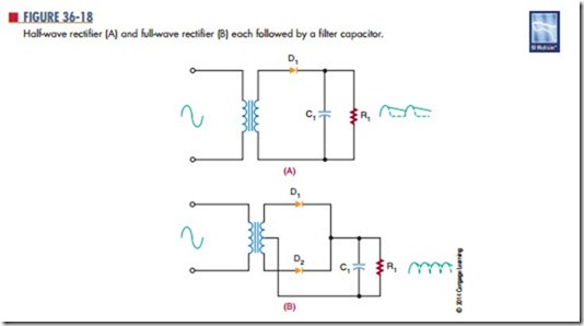
It should be realized that the filter capacitor places additional stress on the diodes used in the rectifier circuit. A half-wave rectifier and a full-wave rectifier, each followed by a filter capacitor, are shown in Figure 36-18. The capacitor charges to the peak value of the secondary voltage and holds this value through- out the input cycle. When the diode becomes reverse biased, it shuts off, and a maximum negative voltage is felt on the anode of the diode. The filter capacitor holds a maximum positive voltage on the cathode of the diode. The difference of potential across the diode is twice the peak value of the secondary. The diode must be selected to withstand this voltage.
The maximum voltage a diode can withstand when reverse biased is called the peak inverse voltage (PIV). A diode should be selected that has a PIV higher than twice the peak value. Ideally, the diode should be operated at 80% of its rated value to allow for changes in the input voltage. This holds true for both the half- wave and the full-wave rectifier but does not hold true for the bridge rectifier.
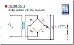
The diodes in a bridge rectifier are never exposed to more than the peak value of the secondary. In Figure 36-19, none of the diodes is exposed to more than the peak value of the input signal. The use of diodes with lower PIV ratings represents another advantage of the bridge rectifier.
Questions
1. What is the purpose of a filter in a power supply?
2. What is the simplest filter configuration?
3. What is the ripple frequency?
4. How is a filter capacitor selected?
5. What adverse effects result from the addition of a filter?
