rectifier circuits
The rectifier circuit is the heart of the power supply. Its function is to convert the incoming AC voltage to a DC voltage. There are three basic types of rectifier circuits used with power supplies: half-wave rectifiers, full-wave rectifiers, and bridge rectifiers.
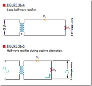
Figure 36-4 shows a basic half-wave rectifier. The diode is located in series with the load. The current in the circuit flows in only one direction because of the diode.
Figure 36-5 shows a half-wave rectifier during the positive alternation of the sine wave. The diode is
forward biased, allowing a current to flow through the load. This allows the positive alternation of the cycle to develop across the load.
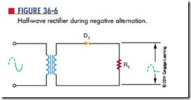
Figure 36-6 shows the circuit during the negative alternation of the sine wave. The diode is now reverse biased and does not conduct. Because no current flows through the load, no voltage is dropped across the load.
The half-wave rectifier operates during only one-half of the input cycle. The output is a series of positive or negative pulses, depending on how the diode is connected in the circuit. The frequency of the pulses is the same as the input frequency and is called the ripple frequency.
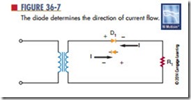
The polarity of the output depends on which way the diode is connected in the circuit (Figure 36-7). The current flows through the diode from cathode to anode. When current flows through a diode, a
deficiency of electrons exists at the anode end, making it the positive end of the diode. Reversing the diode can reverse the polarity of the power supply.
There is a serious disadvantage with the half-wave rectifier because current flows during only half of each cycle. To overcome this disadvantage, a full-wave rectifier can be used.
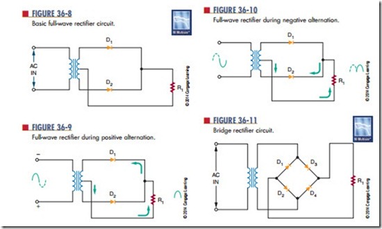
Figure 36-8 shows a basic full-wave rectifier circuit. It requires two diodes and a center-tapped trans- former. The center tap is grounded. The voltages at each end of the transformer are 180° out of phase with each other.
Figure 36-9 shows a full-wave rectifier during the positive alternation of the input signal. The anode of
diode D1 is positive, and the anode of diode D2 is negative. Diode D1 is forward biased and conducts current, whereas diode D2 is reverse biased and does not conduct current. The current flows from the center tap of the transformer, through the load and diode D1, to the top of the secondary of the transformer. This permits R1 the positive half of the cycle to be felt across the load.
Figure 36-10 shows the full-wave rectifier during the negative half of the cycle. The anode of diode D2 becomes positive, and the anode of diode D1 be- comes negative. Diode D2 is now forward biased and conducts. Diode D1 is reverse-biased and does not conduct. The current flows from the center tap of the transformer, through the load and diode D2, to the bottom of the secondary of the transformer.
With a full-wave rectifier, the current flows during both half-cycles. This means that the ripple frequency is twice the input frequency. There is a disadvantage with the full-wave rectifier because the output voltage is half that of a half-wave rectifier for the same trans- former. This disadvantage can be overcome by the use of a bridge rectifier circuit.
Figure 36-11 shows a bridge rectifier circuit. The four diodes are arranged so that the current flows in only one direction through the load.
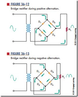
Figure 36-12 shows the current flow during the positive alternation of the input signal. Current flows from the bottom of the secondary side of the trans- former, up through diode D4, through the load, through diode D2, to the top of the secondary of the transformer. The entire voltage is dropped across the load.
Figure 36-13 shows the current flow during the negative alternation of the input signal. The top of the secondary is negative, and the bottom is positive. The current flows from the top of the secondary, down through diode D1, through the load and diode D3, to the bottom of the secondary. Note that the current flows in the same direction through the load as during the positive alternation. Again the entire voltage is dropped across the load.
A bridge rectifier is a type of full-wave rectifier be- cause it operates on both half-cycles of the input sine wave. The advantage of the bridge rectifier is that the circuit does not require a center-tapped secondary. This circuit does not require a transformer to operate. A transformer is used only to step up or step down the voltage or provide isolation.
To summarize the differences in rectifiers: The ad- vantages of the half-wave rectifier are its simplicity and low cost. It requires one diode and a transformer. It is not very efficient, because only half of the input signal is used. It is also restricted to low-current applications.
The full-wave rectifier is more efficient than the half-wave rectifier. It operates on both alternations of the sine wave. The higher ripple frequency of the full- wave rectifier is easier to filter. A disadvantage is that it requires a center-tapped transformer. Its output volt- age is lower than that of a half-wave rectifier for the same transformer because of the center tap.
The bridge rectifier can operate without a trans- former. However, a transformer is needed to step up or step down the voltage. The output of the bridge rectifier is higher than that of either the full-wave or half-wave rectifier. A disadvantage is that the bridge rectifier requires four diodes. However, the diodes are inexpensive compared to a center-tapped transformer.
Questions
1. What is the function of the rectifier in a power supply?
2. What are three configurations for connecting rectifiers to power supplies?
3. What are the differences in operation of the three configurations?
4. What are the advantages of one rectifier configuration over another?
5. Which rectifier configuration represents the best selection? Why?
