FAULT CONDITIONS
Faults can occur during operation of a generator. Protective systems connected to the gen- erator will either provide an alarm or trip the unit when a fault occurs. The following are the most common faults that occur in generators.
Stator Ground (Earth) Faults
The generator stators are grounded through a distribution transformer. A resistor is installed on the secondary side of the transformer to limit the fault current. This arrangement will minimize the damage to the stator core when a fault occurs. Ground fault relays are installed on the generator system. They trip the unit upon a ground fault. Note that mois- ture or contaminated insulation can cause flashover and activation of these relays. Samples of the hydrogen in the stator and the oil in the generator transformer should be obtained fol- lowing such an incident. These samples should be analyzed for hydrocarbons and other gases to help identify the cause of the fault and its location.
Stator Phase-to-Phase Faults
Large generators are normally connected to the grid via a step-up transformer. Phase- segregated bus bars connect the generator to the step-up transformers. Thus, the probability of a phase-to-phase fault is low. However, if a fault of this type occurs in the stator, it will cause extreme damage. The connections at the ends of the windings are the areas most prone to phase-to-phase faults. In these areas, nylon hoses provide cooling water to the end windings. If a conducting debris is left in the generator during maintenance, it can penetrate through the insulation, leading to a phase-to-phase fault. Hence, it is essential to take great care to prevent any debris from being left in the generator.
Stator Interturn Faults
Interturn faults are normally caused by debris on the winding, fatigue failure of the insulator, moisture condensation at the end windings, contamination of the stator cooling water, etc. Interturn faults generate high recirculating currents and do considerable damage at the loca- tion of the fault. There is no protection for this type of a fault. However, if the damage progresses, a ground (earth) or a phase-to-phase fault will occur. The protective systems will trip the generator in this case.
Negative Phase Sequence Currents
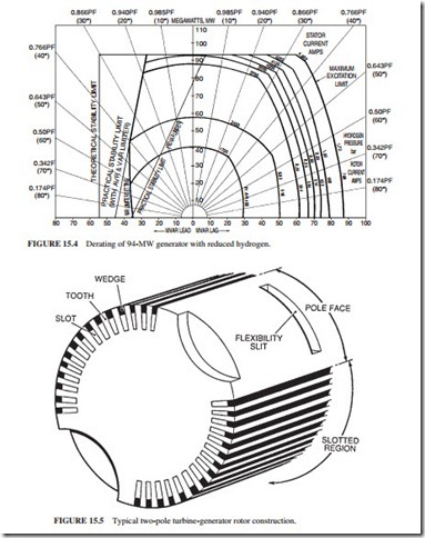
Negative sequence currents occur due to unbalanced loading or unbalanced faults. These currents flow in the rotor core or slot wedges (Fig. 15.5), causing unacceptable heating in
a localized area of the rotor. They can also cause cracks in the rotor in extreme cases. The protective systems will trip the rotor when potentially damaging negative sequence currents are generated. Alarms annunciate when low-level negative sequence currents occur, to warn operators that the load is unbalanced. It is necessary to identify and eliminate the cause of unbalance. The grid system should be notified of this condition because the cause of unbalance could be outside the power station. If the negative sequence currents are caused by an open circuit in a major interconnection, the unbalance will increase, leading to a unit trip. The negative sequence current will be shared by all the generators connected to the grid. Identical machines will share the current equally. Thus, they will all trip simulta- neously at a specified value of the negative sequence current. This will lead to a further increase in the negative sequence current on the generators that are still connected to the grid.
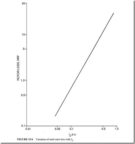
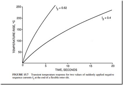
Figure 15.6 illustrates the variation of the total rotor loss with negative sequence current I2 per unit (i.e., portion of the rotor current) for a typical rotor. Figure 15.7 illustrates the variation of rotor temperature for two values of negative sequence currents I2, suddenly applied at the end of a rotor flexibility slit. These results were obtained from manufacturers’ tests.
Loss of Generator Excitation
The loss of excitation causes a decay in the rotor flux and an eventual loss of synchronism. The unit operates then as an induction generator. It draws reactive power from the system. The generator terminal voltage will drop. This could result in impairment of some of the auxiliary loads supplied from the generator. The protective systems trip the generator when this condition is detected. These systems rely on an impedance relay that monitors the gen- erator impedance as seen from its terminals. The generator impedance changes when the excitation is lost. The impedance relay detects this change and trips the machine.
During recoverable transient conditions, there is a significant change in the generator impedance. Thus, a time delay is incorporated in the protective system, using the impedance relay to prevent tripping of the unit during recoverable transient conditions. Some generator protective systems trip the unit on loss of excitation when a large input of reactive power is detected. A time delay is also incorporated in this protective system to prevent unit trip during recoverable transient conditions.
Pole Slipping
Pole slipping in a generator is caused by loss of synchronism due to one of the following conditions:
● Inability of the excitation system to maintain the torque required for synchronism
● A system fault
This event causes large variations in voltage, active power, and reactive power delivered by the generator. It could also trip the auxiliary system motors, leading to a unit trip. This type of a shutdown could cause damage to the plant because it is nonsequenced. This event would also have an effect on the load and other generating plants connected to the grid. The transmission circuit protection could also operate indiscriminately during this event due to the large variation in power transmitted. This will lead to disconnection of some generating units from the grid. However, pole-slipping events are rare due to grid operating criteria. Thus, pole-slipping protection is not installed on most generating units.
Rotor Faults
A static or a rotating rectifier supplies dc power (excitation) to the windings of a generator rotor. The excitation voltage and current of a typical 600-MW plant are 550 V and 4500 A, respectively. The excitation circuit is insulated from the ground. The ground fault alarm annunciates when a ground fault having a resistance less than 20,000 .!1 occurs. A ground fault can occur due to carbon dust on the slip ring insulation, or to moisture on the insula- tion of the excitation circuit. In this case, it is necessary to isolate the rotor windings by removing the carbon brushes to identify the location of the fault.
A ground fault can also occur due to a failure of the rotor winding insulation. However, one ground fault will not cause significant damage to the rotor. If a second ground fault occurs at a different location, a short circuit will develop in the winding, leading to flow of currents through the rotor forging or end rings. This current could cause extensive damage to the rotor. A generator having a high-resistance rotor ground fault can continue to operate with the aid of a ground fault protection system. This system monitors the resistance of the ground fault and its position. It trips the unit when the resistance of the ground fault drops below a specified value or when the location of the ground fault changes.
The three mechanisms of insulation failure are
● Bridging of the insulation by foreign material.
● Mechanical failure of the insulation.
● Copper dust generated by wear of the copper winding due to movement within the slots. Most of the copper dust is generated when the machine is rotated slowly by the turning gear. During this period, the copper windings contract because the machine is cold. There is more space for the windings to move within the rotor slots. A significant amount of copper dust could be generated if the machine is left on turning gear for an extended time.
A ground fault can occur by any of the mechanisms mentioned earlier. The current at the location of the fault could overheat the insulation and damage the windings. The dam- age could also spread to adjacent windings. The automatic voltage regulator (AVR) will increase the rotor current to compensate for the fault. Thus, a ground fault may not necessarily be noticed. The fault could also disappear when the unit is shut down due to move- ment of the insulation within the slot.
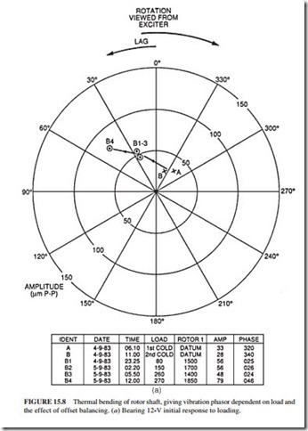
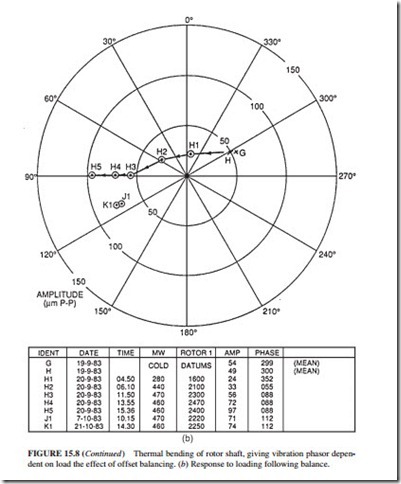
The effects of one set of shorted turns will be limited to one pole only. The rotor magnetic field will become unbalanced, leading to vibration. The magnitude of the vibration will vary with the rotor current. Since the current flowing in the shorted turns is lower, less heat is generated by them than by other turns. This will cause a thermal bend in the shaft that produces vibration. The magnitude of the vibration increases with the rotor current. These vibrations can limit the rotor currents, thereby limiting the capability of the genera- tor. In this case, it is necessary to repair the rotor at the earliest opportunity. However, if continued operation of the unit is necessary until a suitable outage, then off-loading balance (known as offset balancing) can be done to maintain the vibration levels within acceptable limits. Figure 15.8a illustrates the vibration characteristics of a rotor prior to offset balancing. The cold vibration datum was at B (around 30 m peak to peak). The vibration level changed to B4 (around 85 m peak to peak) when the rotor current reached 1850 A.
Following offset balancing, the cold vibration datum (Fig. 15.8b) moved to G (around 55 m peak to peak). The vibration level changed to H4 (around 70 m peak to peak) when the rotor current reached 2470 A. Thus, the offset balancing has allowed the generator to deliver higher load.
The in-core leakage flux detector (known also as the search coil) detects shorted turns in the rotor. It is installed on the stator in the air gap between the stator and the rotor. Figure
15.9 illustrates the voltage output waveform of a search coil. The tooth harmonic waveform is different for each pole. Figure 15.9a illustrates faults on coils D and F. Figure 15.9b illustrates additional shorted turns that developed on coil D.
