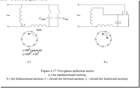
When only single phase supply is available, two-phase windings are used. One is called the main winding (M) and the other, connected in series with a capacitor, is called the auxiliary winding (Aux).
The two windings are displaced from each other, as shown earlier in this chapter, by 900 (electrical), and are symmetrized for a certain speed (slip) by choosing the correct value of the capacitance. Symmetrization for start (slip = 0) with a capacitance Cstart and again for rated slip with a capacitance Crun is typical (Cstart >> Crun).
When a single capacitor is used, as a compromise between acceptable starting and running, the two windings may be shifted in space by more than 900 (1050 to 1100) (Figure 4.17).
Single capacitor configurations for good start are characterized by the disconnection of the auxiliary winding (and capacitor) after starting. In this case the machine is called capacitor start and the main winding occupies 66% of stator periphery. On the other hand, if bi-directional motion is required, the two windings should each occupy 50% of the stator periphery and should be identical.
Two-phase windings are used for low power (0.3 to 2 kW) and thus have rather low efficiency. As these motors are made in large numbers due to their use in home appliances, any improvement in the design may be implemented at competitive costs. For example, to reduce the mmf harmonics content, both phases may be placed in all (most) slots in different proportions. Notice that in two-phase windings multiple of three harmonics may exist and they may deteriorate performance notably.
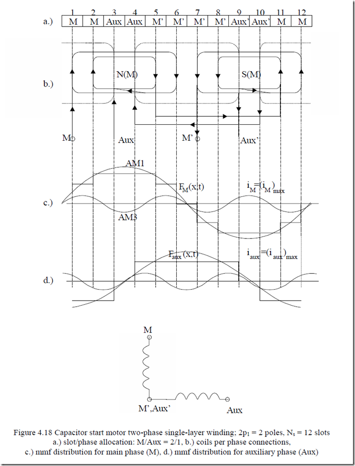
Let us first consider the capacitor-start motor windings.
As the main winding (M) occupies 2/3 of all slots (Figure 4.18a, b), its mmf distribution (Figure 4.18c) is notably different from that of the auxiliary winding (Figure 4.18d). Also the distribution factors for the two phases (Kq1M and
Kq1Aux) are expected to be different as qM = 4 and qAux = 2.
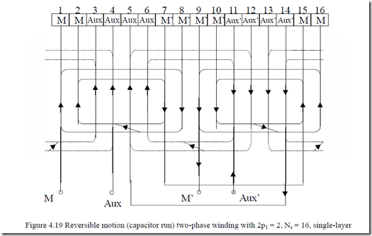
For Ns = 16, 2p1 = 2, the above winding could be redesigned for reversible motion where both windings occupy the same number of slots. In that case the windings look like those shown in Figure 4.19.
The two windings have the same number of slots and same distribution factors and, have the same number of turns per coil and same wire gauge only for reversible motion when the capacitor is connected to either of the two phases. The quantity of copper is not the same since the end connections may have slightly different lengths for the two phases.
Double-layer windings, for this case (qM = qAux – slot/pole/phase), may be built as done for three-phase windings with identical chorded coils. In this case, even for different number of turns/coil and wire gauge–capacitor run motors– the quantity of copper is the same and the ratio of resistances and self inductances is proportional to the number of turns/coil squared.
As mentioned above and in Chapter 2, capacitor induction motors of high performance need almost sinusoidal mmf distribution to cancel the various bad space harmonic influences on performance.
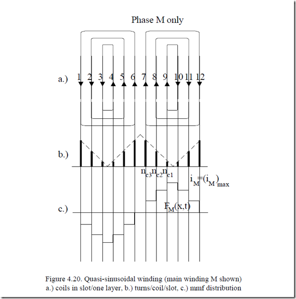
One way to do it is to build almost sinusoidal windings; that is, all slots contain coils of both phases but in different proportions (number of turns) so as to obtain sinusoidal mmf. An example for the 2 pole 12 slot case is given in Figure 4.20.
Now if the two windings are equally strong, having the same amount of copper, the slots could be identical. If not, in the case of a capacitor-start, only auxiliary winding, part of the slots may have a smaller area. This way, the motor weight may be reduced. It is evident from Figure 4.20c that the mmf distribution is now much closer to a sinusoid.
Satisfactory results may be obtained for small power resistor started induction motors if the distribution of conductor/slot/phase runs linear rather than sinusoidal with a flat (open) zone of one third of a pole pitch. In this case, however, the number of slots Ns should be a multiple of 6p1.
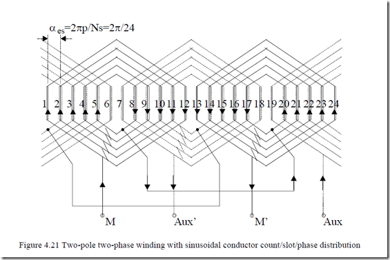
An example of a two one-layer sinusoidal winding is shown in Figure 4.21, for 2p1 = 2, Ns = 24 slots
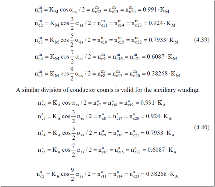
Similar to Figure 4.20b, the number of turns/coils for the main winding in slots 1 to 5 is
Related posts:
Incoming search terms:
- lslot countig in winding 24 slot
- two phase motor windings
- 2 phase AC winding who to trun srating and running slot com
- 2 phase motor 5 layer 24 slot main auxilirey winding diagram
- 24 slot single phase motor winding diagram
- madhani running satetar winding wire and tarn slot 24
- Single phase induction motor stator winding drawing
