Objectives
After studying this unit, the student will be able to:
• Describe the operation of float switches
• List the sequence of operation for sump pumping or tank filling
• Draw wiring symbols for float switches
A float switch is used when a pump motor must be started and stopped according to changes in the water (or other liquid) level in a tank or sump. Float switches are designed to provide au tomatic control of ac and de pump motor magnetic starters and automatic direct control of light motor loads.
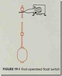
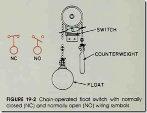
The operation of a float switch is controlled by the upward or downward movement of a float placed in a water tank. The float movement causes a rod-operated, figure 19-1, or chain and counter weight, figure 19-2, assembly to open or close electrical contacts. The float switch contacts may be either normally open or normally closed and may not be submerged. Float switches may be connected to a pump motor for tank or sump pumping operations or tank filling, depending on the contact arrangement.
REVIEW QUESTIONS
1. Describe the sequence of operations required to (a) pump sumps and (b) fill tanks.
2. Draw the normally open and normally closed contact symbols for a float
switch.

