MAGNETIC-VANE METERS
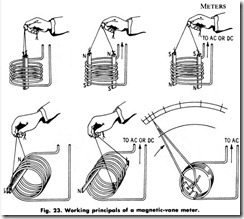
This type of ac and de instrument, sometimes called a moving-iron instrument or a moving-iron-vane instrument, is often used for am meters and voltmeters. This instrument depends for its operation on the reactions resulting from the current in one or more fixed coils acting upon one or more pieces of soft iron or magnetically similar material in the moving system. The moving-iron principle is illustrated in Fig. 23.
If two similar and adjacent iron bars are similarly magnetized, a repelling force is developed between them which tends to move them apart. In the moving-iron instrument, this principle is used by having one bar fixed in space and by pivoting the second so that it will tend to rotate when the magnetizing current flows. A spring attached to the moving vane opposes the motion of the vane and permits the scale to be calibrated in terms of the amount of current flowing. When current flows through the solenoid, the plunger is drawn into the coil and a measurable deflection of the instrument pointer is obtained. Because, however, of high power consumption, sensitivity to slight zero shifts, scale difficulties, etc., this type of movement is presently used only in less expensive instruments.
Repulsion Type
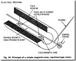
This instrument (Fig. 24) differs in construction principles from the previously described moving-iron-vane instrument in that the magnetic vane embedded in the side of the coil has definite Nand S poles at the points shown. The moving vane will be magnetized by induction, with the polarities as shown. Notice that the north pole of the moving vane is nearest to the north pole on the piece of magnetic material embedded in the coil, and that the south poles are similarly placed. Hence, the vane tends to move away or to be repelled from the stationary magnetic piece .
If alternating current is applied to the instrument, the two vanes will simultaneously change polarities as the current varies throughout the cycle thus, the instrument also operates on alternating current. In fact, it is in ac measurements that the instrument finds its greatest application.
Induction Type
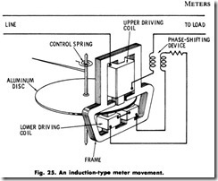
This type of instrument depends for its operation on the reactions between a magnetic flux (or fluxes) set up by one or more currents in fixed windings, and electric currents set up by electromagnetic induc tion in conducting parts of the moving system. The construction of a typical induction instrument is shown in Fig. 25. The instrument consists primarily of a field structure with associated windings into which a rotating disc of aluminum is placed. The disc will tend to rotate when an alternating current of the proper phase relation is applied to the two coils. If a spring is inserted on the disc shaft to counteract the movement of the disc, and a pointer is added, its movement will indicate the value of the current flowing through the instrument.
This instrument can only be used on alternating current. If a direct current is applied, the only time voltage would be induced in the disc would be at the instant the circuit is opened or closed. Thus, the disc will tend to move forward and then drop back to its initial position when a steady-state condition is reached .
The disc must be made of aluminum or copper, or of some other aterial of high electrical conductivity. Since all these materials pos sess appreciable temperature coefficients of resistance, changes in temperature will materially affect the readings unless carefully com pensated for in other parts of the circuit. This has limited the usefulness of these devices to a considerable extent.
Induction Watt-Hour Meter
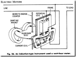
If the spring and pointer are omitted in the assembly shown in Fig. 25, and magnets placed at the edge of the disc as in Fig. 26, the disc will cut lines of magnetic flux from the magnets located at its periphery, and the currents induced will tend to reduce the speed of the disc.
The effect of temperature on such an arrangement is not nearly so pronounced as in the case of the spring-controlled induction instrument. As the temperature increases, both the induced current actuating the disc and the eddy currents caused by the damping magnets tend to decrease in the same proportion. If the connections are changed and a counter connected by suitable gearing added to count the total revolu tions of the disc, the basic elements of the induction watt-hour meter are obtained.
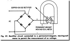
A rectifier instrument is principally the combination of a meter sensitive only to direct current and a rectifying device whereby alter nating currents or voltages may be measured. By inserting a rectifier in an ac circuit, as shown in Fig. 27, it will be possible to use the previously described permanent-magnet, moving-coil type of meter to measure the value of an alternating current.
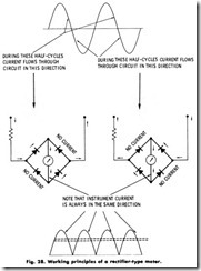
A rectifier instrument may be equipped with any one of several types of rectifying devices. The one most commonly used is the copper-oxide type, which works on the principle that the electrical resistance of a properly formed layer of copper oxide on a copper surface depends on the polarity of the applied voltage. The most common method used is to arrange four copper plates in a bridge connection, as shown in Fig. 28. This bridge arrangement rectifies every half -cycle of the ac wave and is called a full-wave rectifier.
When using rectifier instruments, it should always be borne in mind what the instrument really indicates, regardless of how the scale may be marked. A permanent-magnet, moving-coil type of instrument indicates average values, shown by the lower line in Fig. 28. On ac circuits, however, the root-mean-square (rms) value is the quantity generally required. This value is shown by the upper line.
For a sine wave, the ration between rms value and average value is 1.11, and the meter scale is marked directly in terms of the rms value. For other wave shapes this ratio is different, and hence a rectifier instrument reads rms quantities correctly only for the wave shape for which it is calibrated. This point must be kept in mind when using rectifier instruments to measure nonsinusoidal quantities, such as the outputs of constant-voltage transformers. Fortunately, the errors result ing from this condition are generally less than 10% of full-scale value.
Some other points to be kept in mind when using rectifier-type instruments are:
1. Some aging of the rectifiers occurs in service. For this reason, the stated accuracy of rectifier instruments is often given as 15% of full scale. Consecutive readings, however, will often duplicate to within a few tenths of 1%.
2. Exposure of the rectifier instrument to high temperatures or to chemical vapors may shorten the life of the rectifier.
3. The circuit of the instrument itself should never be opened when the rectifier is connected to the line, since this may allow full line voltage to be impressed on the rectifier plates and it may damage them.
Despite these considerations, rectifier instruments play a very useful part in present-day measurements, because the permanent-magnet, moving-coil construction gives a higher sensitivity and a more uniform scale than is possible to secure with a moving-iron or a dynamometer type.
Clamp Ammeters
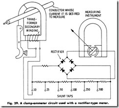
Another type of instrument which is frequently employed in con junction with a rectifier is the clamp ammeter. It, however, is not a precision instrument, but is used for rough approximations of current in conductors and in motor or transformer leads. Principally, the instrument consists of a current transformer of the inserted-primary type, and a rectifier connected to a permanent-magnet, moving-coil type of instrument . As shown in Fig. 29, the conductor forms the transformer primary winding, which induces a current in the transformer secondary.
Various ranges are obtained by using an external multiplier arrange ment. When connected as shown, a small proportional current is derived from the line current through the use of the hinged-core current transformer. This secondary current is then connected to a suitable tap on the multiple-range rectifier-type meter to give the reading. The rectifier instrument is made into a multiple-range device through the use of the multirange series shunt. In this combination, it is possible to measure the current in any conductor by using the proper taps on the series shunt.
